
Golf club head and golf club

Active Publication Date: 2011-05-19
BRIDGESTONE SPORTS
View PDF18 Cites 35 Cited by
  • Summary
  • Abstract
  • Description
  • Claims
  • Application Information

AI Technical Summary

Benefits of technology

[0008]An object of the present invention is to solve the above-mentioned problem and provide a golf club and a head that can perform a phase positioning of a hosel column and can control properties such as a lie angle, a slice angle and a goose neck shape with good reproducibility. Furthermore, another object of the present invention is to provide a head in which an excessive increase in weight of the heel side is prevented in one aspect thereof.

Problems solved by technology

However, when the phase has changed, an original phase becomes unknown, whereby, even if it is thought that a control of a direction of the original phase is satisfactory, it is difficult to accurately return to (reproduce) the original phase.
Furthermore, since the golf club head has a configuration in which the overall hosel joint is fitted into the hosel, the diameter of the hosel increases, which makes the weight of the head on the heel side become excessive.

Method used


Image

  • Golf club head and golf club
  • Golf club head and golf club
  • Golf club head and golf club

Examples


first embodiment

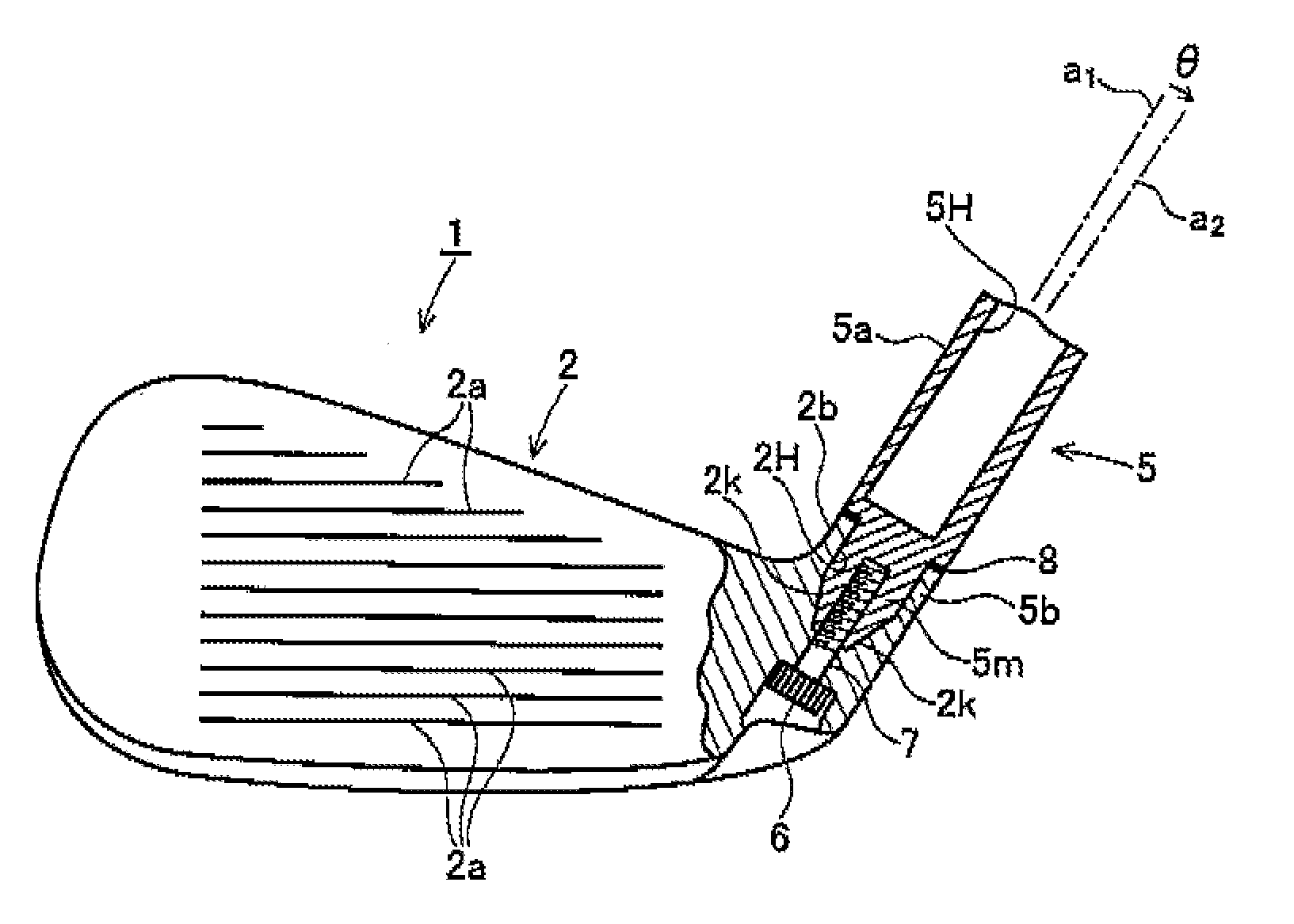
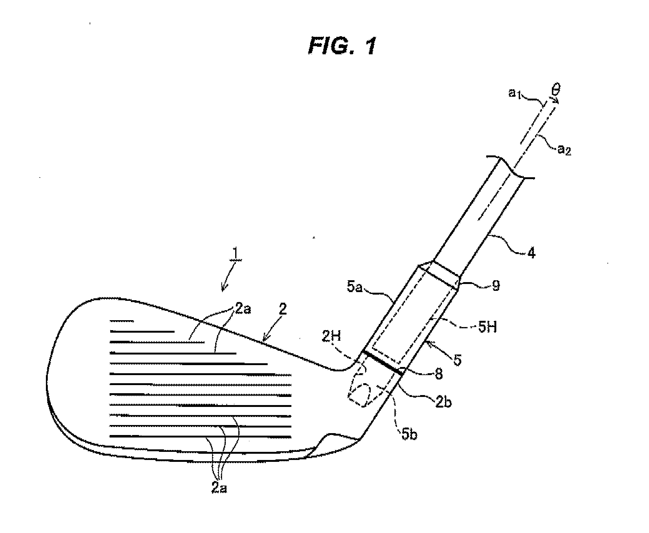
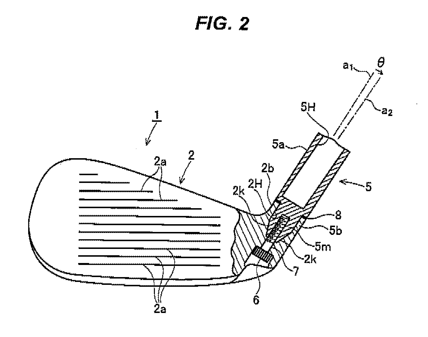
[0052]Hereinafter, a first embodiment will be described with reference to FIGS. 1 to 7.

[0053]In this embodiment, a head 1 is an iron type golf club head. The head 1 has a head main body 2, and a hosel column 5 which is attachably and detachably attached to the head main body 2. A plurality of score lines 2a is provided on a face surface of the head main body 2 in a horizontal direction. A hosel column inserting hole 2H is recessed from the upper end surface of a hosel portion 2b. The hosel column inserting hole 2H has a cylindrical shape with an open upper end and a closed lower end and extends in a inserting direction of the shaft 4. An inner peripheral surface of hosel column inserting hole 2H is a cylindrical portion except for a lower part thereof. An outer peripheral edge of the upper end surface of the hosel portion 2b has a circular shape which is coaxial with the hosel column inserting hole 2H.

[0054]An inner peripheral surface on an inner side further than the cylindrical po...

second embodiment

[0076]FIG. 8 is a perspective view of a hosel column 5A which is used in a FIGS. 9 and 10 are front views of a head using the hosel column 5A.

[0077]The hosel column 5A also includes the trunk portion 5a and the leg portion 5b in the same manner as the hosel column 5, and the shaft inserting hole 5H is provided on the trunk portion 5a.

[0078]In the present embodiment, the outer peripheral surface of the trunk portion 5a is in common with the axis center line a2 of the shaft inserting hole 5H. In addition, the axis center line a2 slopes with respect the axis center line a1 of the hosel column inserting hole 2H by angle θ.

[0079]The most sloped side of the outer peripheral surface of the trunk portion 5a intersects the lower end surface of the trunk portion 5a by (90°-θ).

[0080]Another configuration of the head 1 in which the hosel column 5A is installed in the head main body 2 is the same as the head of the above-mentioned first embodiment, and the hosel column 5A is fixed by the bolt ...

third embodiment

[0082]FIG. 11 is a perspective view of a hosel column 5B used in a FIG. 12 is a front view of a head which uses the hosel column 5B. FIG. 13 is a front view of the head with a phase of the hosel column 5B being changed from FIG. 12 by 180°. FIGS. 14 and 15 are plane views of the head with the phase of the hosel column 15B being respectively changed from FIG. 12 in a clockwise direction and in a counterclockwise direction by 90°.

[0083]The hosel column 5B also includes the trunk portion 5a and the leg portion 5b in the same manner as the hosel columns 5 and 5A, and the shaft inserting hole 5H is provided on the trunk portion 5a.

[0084]In the present embodiment, as shown in FIG. 11, the axis center line a2 of the shaft 4 and the shaft inserting hole 5H is substantially parallel to the axis center line a1 of the leg portion 5b and the hosel column inserting hole 2H, and is disposed so as to be separated from the axis center line a1 by a predetermined distance D. That is, the hosel colu...


PUM


Abstract

A golf club head includes: a head main body formed with a hosel column inserting hole; a hosel column which is formed with a shaft inserting hole and is installed on the hosel column inserting hole; a bolt inserting hole penetrating from a sole side of the head main body to the hosel column inserting hole; and a bolt which is inserted into the bolt inserting hole and is screwed into the hosel column, wherein: the hosel column includes a trunk portion provided with a shaft inserting hole, and a leg portion which protrudes from a lower end surface of the trunk portion and is inserted into the hosel column inserting hole; and at least a lower end side of the leg portion and an inner portion of the hosel column inserting hole are polygonal sectional shape portions and are engaged with each other.

Description

BACKGROUND[0001]1. Field of the Invention[0002]The present invention relates to a golf club and a head thereof. Particularly, the present invention relates to a golf club and a head thereof capable of easily performing control of properties such as a lie angle, a slice angle and a goose neck shape.[0003]2. Description of the Related Art[0004]A golf club has a head attached to a front end portion of a shaft. A grip is installed in a proximal end side of the shaft.[0005]In a general golf club head of the related art, a hosel port is directly provided on a hosel portion of the head, and a shaft is inserted into the hosel port and is fixed by an adhesive. In addition, as the adhesive, an epoxy-based adhesive is generally used. When the shaft is exchanged, the shaft is pulled out by heating the hosel portion to destroy a structure formed of an epoxy resin hardening product.[0006]In JP-A-2000-5349, there is described a golf club in which a hosel joint is bonded to a front end of the shaft...

Claims


Application Information

Patent Timeline
IPC IPC(8): A63B53/02A63B53/04A63B53/00A63B53/06A63B102/32
CPCA63B53/02A63B2053/023A63B2053/021A63B53/021A63B53/023A63B60/00
Inventor SATO, FUMIAKIWADA, KOZUEMATSUNAGA, HIDEO
Owner BRIDGESTONE SPORTS
Features
  • Generate Ideas
  • Intellectual Property
  • Life Sciences
  • Materials
  • Tech Scout
  • Unparalleled Data Quality
  • Higher Quality Content
  • 60% Fewer Hallucinations
Learn More