Packaging Locking & Indication System

Inactive Publication Date: 2011-05-26
MILAN INNOVATION
View PDF23 Cites 19 Cited by
  • Summary
  • Abstract
  • Description
  • Claims
  • Application Information

AI Technical Summary

Benefits of technology

[0009]A particular advantage of the present invention is that rather than relying on the end user to correctly identify, remember and act in accordance with the “Use By” or “Period after Opening” information displayed on a product package, or interpret, act in accordance with and in some cases ac

Problems solved by technology

In a third aspect, by similar means,

Method used


Image

  • Packaging Locking & Indication System
  • Packaging Locking & Indication System
  • Packaging Locking & Indication System

Examples


first embodiment

[0024]the invention will now be described by way of example only with reference to FIGS. 1 to 8 of the accompanying drawings, in which:

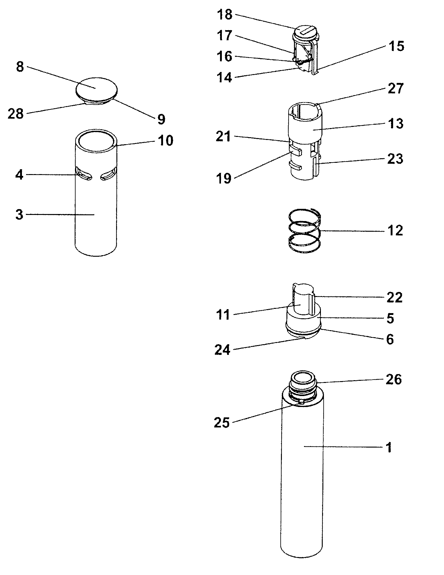
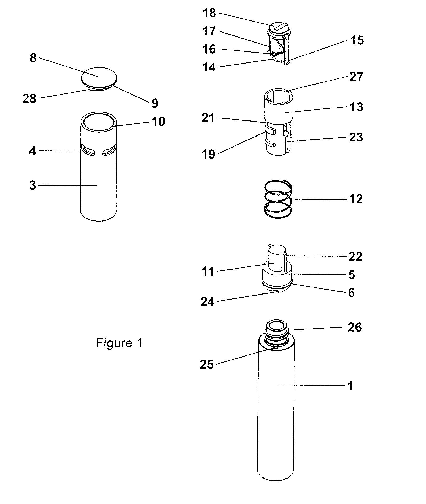
[0025]FIG. 1 shows, in perspective, the constituent parts of a product package consisting of a container with a screw cap incorporating an electronic-timer-and-latch-type locking system with visual indicator.

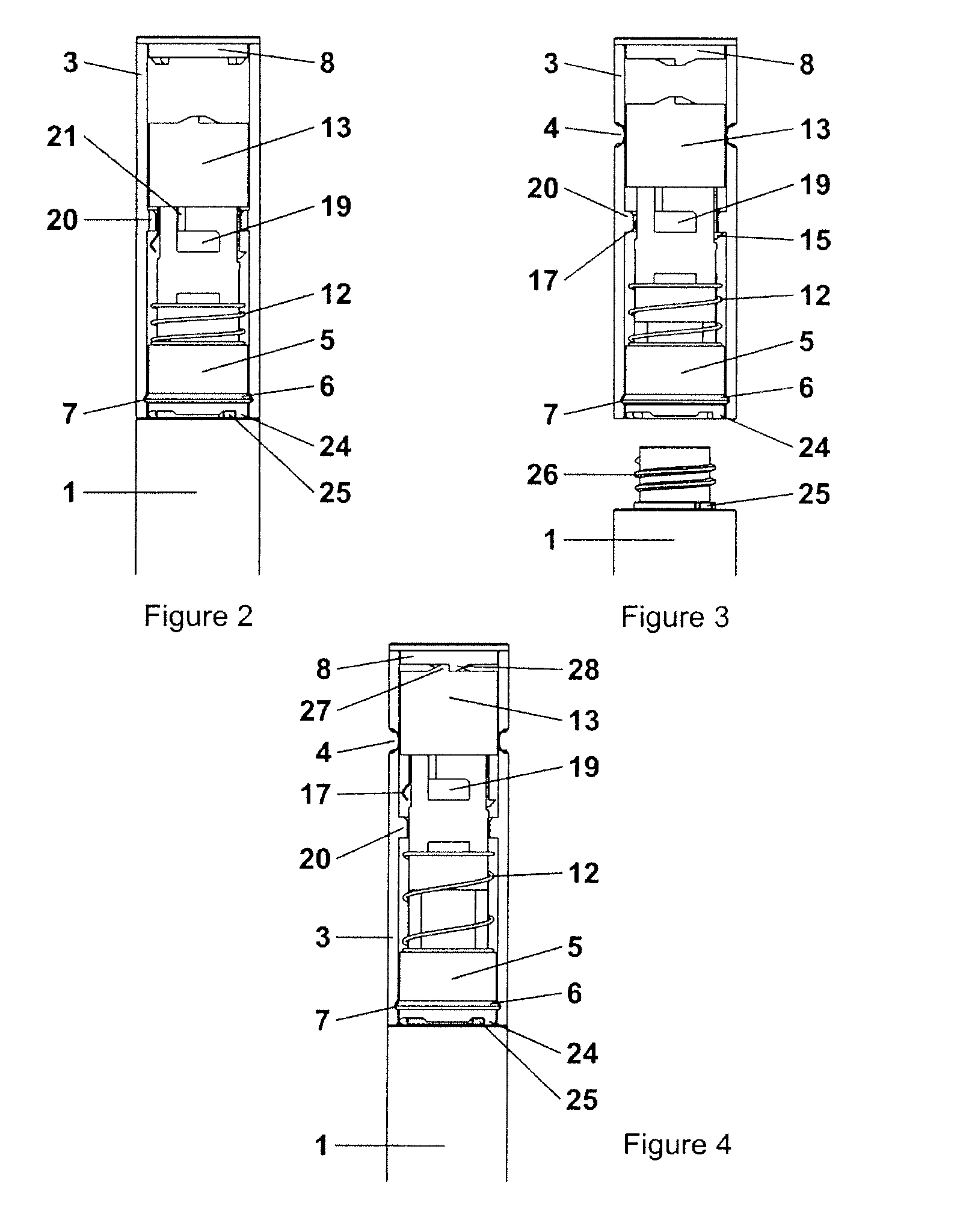
[0026]FIG. 2 shows, with the outer cap in section, the closed product container prior to the activation of the electronic-timer-and-latch-type locking system.

[0027]FIG. 3 shows, with the outer cap in section, the open product container with the electronic-timer-and-latch-type locking system activated.

[0028]FIG. 4 shows, with the outer cap in section, the container and screw cap locked together by means of the electronic-timer-and-latch-type locking system.

[0029]FIG. 5 shows the closed product container incorporating an electronic-timer-and-latch-type locking system with indication apertures.

[0030]FIG. 6 shows the indication displayed in the indic...

second embodiment

[0043]the invention will now be described by way of example only with reference to FIGS. 9 to 16 of the accompanying drawings, in which:

[0044]FIG. 9 shows, in perspective, the constituent parts of a product package consisting of a container with a screw cap incorporating a spring-loaded piston, cylinder and gas-permeable-barrier-type, time-temperature-dependant locking system with visual indicator.

[0045]FIG. 10 shows, with the outer cap in section, the closed product container prior to the activation of the spring-loaded piston, cylinder and gas-permeable-barrier-type, time-temperature-dependant locking system.

[0046]FIG. 11 shows, with the outer cap in section, the open product container with the spring-loaded piston, cylinder and gas-permeable-barrier-type, time-temperature-dependant locking system activated.

[0047]FIG. 12 shows, with the outer cap in section, the container and screw cap locked together by means of the spring-loaded piston, cylinder and gas-permeable-barrier-type, t...

third embodiment

[0060]the invention will now be described by way of example only with reference to FIGS. 17 to 24 of the accompanying drawings, in which:

[0061]FIG. 17 shows, in perspective, the constituent parts of a product package consisting of a container with a screw cap incorporating a viscous fluid and non-sealed-piston-type, time-temperature-dependant locking system with visual indicator.

[0062]FIG. 18 shows, with the outer cap in section, the closed product container prior to the activation of the viscous fluid and non-sealed-piston-type, time-temperature-dependant locking system.

[0063]FIG. 19 shows, with the outer cap in section, the open product container with the viscous fluid and non-sealed-piston-type, time-temperature-dependant locking system activated.

[0064]FIG. 20 shows, with the outer cap in section, the container and screw cap locked together by means of the viscous fluid and non-sealed-piston-type, time-temperature-dependant locking system.

[0065]FIG. 21 shows the closed product co...


PUM


Abstract

For use in dispensing a material that has a limited period of utility, a novel device comprises a first part (1) containing the material and a second part (2), wherein the first and second parts have mutual engagement means (6,7) and can be disengaged to allow the material to be dispensed, wherein the device includes, located within the device, control means that can be activated to initiate a time-controlled period of use and that, at the end of that period, causes the first and second parts to be permanently engaged.

Description

FIELD OF THE INVENTION[0001]The present invention relates to the packaging of non-durable products such as cosmetics, skin care products, sun care products, toiletries, foodstuffs, beverages and certain pharmaceutical products and other non-durable products, principally in containers with reusable closures, the quality and efficaciousness of which deteriorate with respect to time and or exposure to excessive temperature, humidity, light and air and or to the presence of microbes from the point of manufacture or from the first occasion at which the package is opened by the end user.BACKGROUND OF THE INVENTION[0002]The quality and efficaciousness and in some instances safety of non-durable products deteriorate over time, requiring the packaging within which they are contained to display a “Use By”, “Best Before”, “Expiration” or other date to indicate when the product will become unsuitable for use. Many products deteriorate at an accelerated rate once the packaging within which they ...

Claims


Application Information

Patent Timeline
IPC IPC(8): B67D7/08B67D7/06B67B1/00
CPCB65D79/02B65D2203/12G04F1/02G04F1/005G04F1/00A45D34/00B05B11/0027
Inventor MILAN, GUY DIMITRI
Owner MILAN INNOVATION
Why Eureka
Try Eureka