Foam dispensing apparatus

Active Publication Date: 2011-05-26
BASF AG
View PDF28 Cites 22 Cited by
  • Summary
  • Abstract
  • Description
  • Claims
  • Application Information

AI Technical Summary

Benefits of technology

[0010]The present invention includes a foam dispensing apparatus for dispensing a mixture of a resin component and an isocyanate component. The foam dispensing apparatus comprises a resin line for carrying the resin component and an isocyanate line for carrying the isocyanate component. The foam dispensing apparatus further comprises a nozzle for dispensing the resin and isocyanate components from the foam dispensing apparatus. A manifold is connected to the nozzle. The manifold defines a resin duct in communication with the resin line and the nozzle for directing the resin component toward the nozzle and an isocyanate duct in communication with the isocyanate line and the nozzle for directing the isocyanate component toward the nozzle. At least one valve is connected to the resin and isocyanate lines and is moveable between an open position allowing flow through the resin and isocyanate lines and a closed position preventing flow through the resin and isocyanate lines. The valve is disposed exterior to the manifold and the flow is unregulated in the manifold for reducing maintenance of the manifold.
[0011]The present invention also includes a foam dispensing system for dispensing a mixture of a resin component and an isocyanate component. The foam dispensing system comprises a source of resin component and a source of isocyanate component. The foam dispensing system further comprises a nozzle for mixing the resin and isocyanate components and a manifold connected to the nozzle. The manifold defi

Problems solved by technology

However, the flow rate of the polyurethane being dispensed from the foam dispensing apparatus is relatively low, which disadvantageously increases the amount of time to dispense a given amount of polyurethane foam.
However, high pressure systems include larg

Method used


Image

  • Foam dispensing apparatus
  • Foam dispensing apparatus
  • Foam dispensing apparatus

Examples


Embodiment Construction

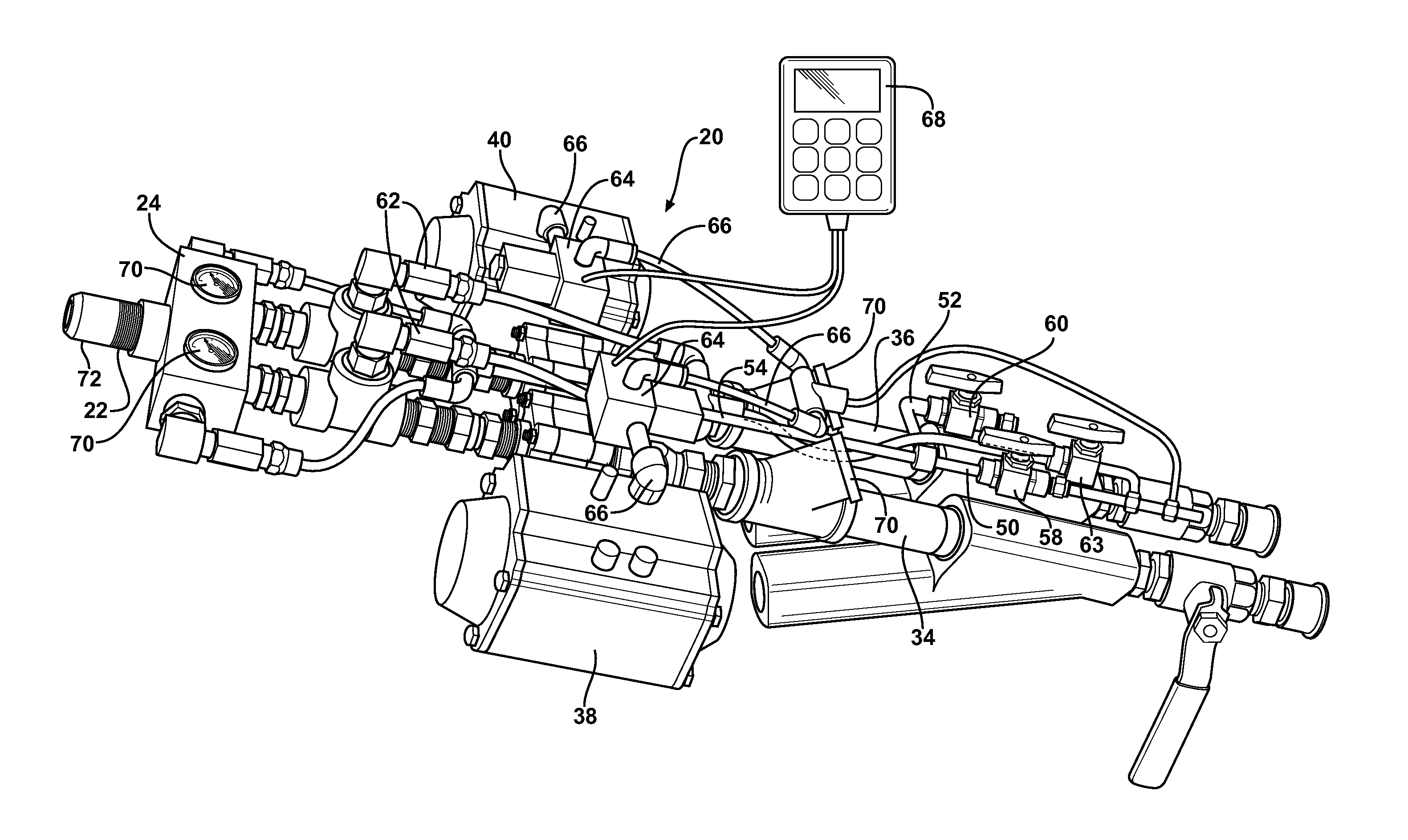
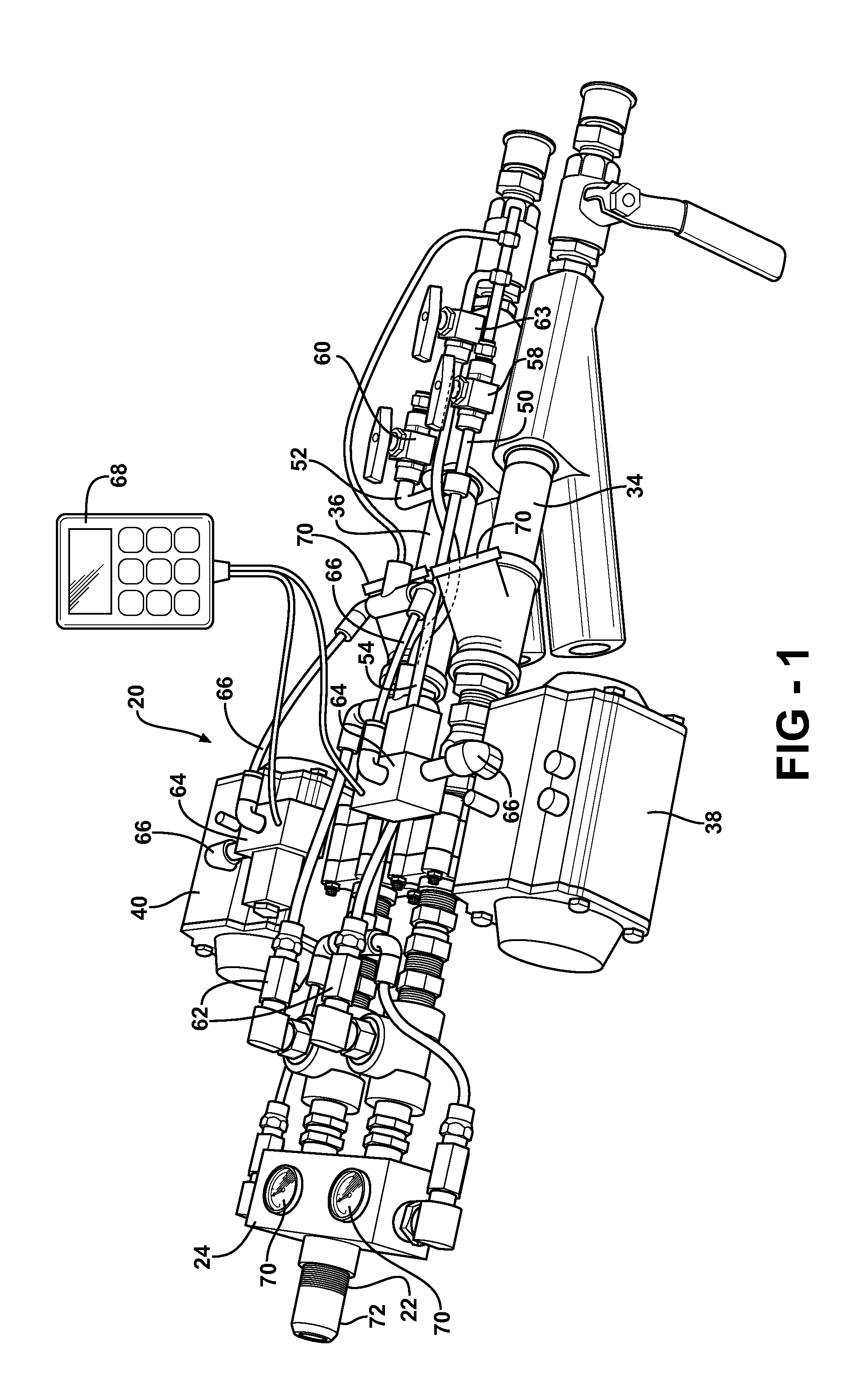
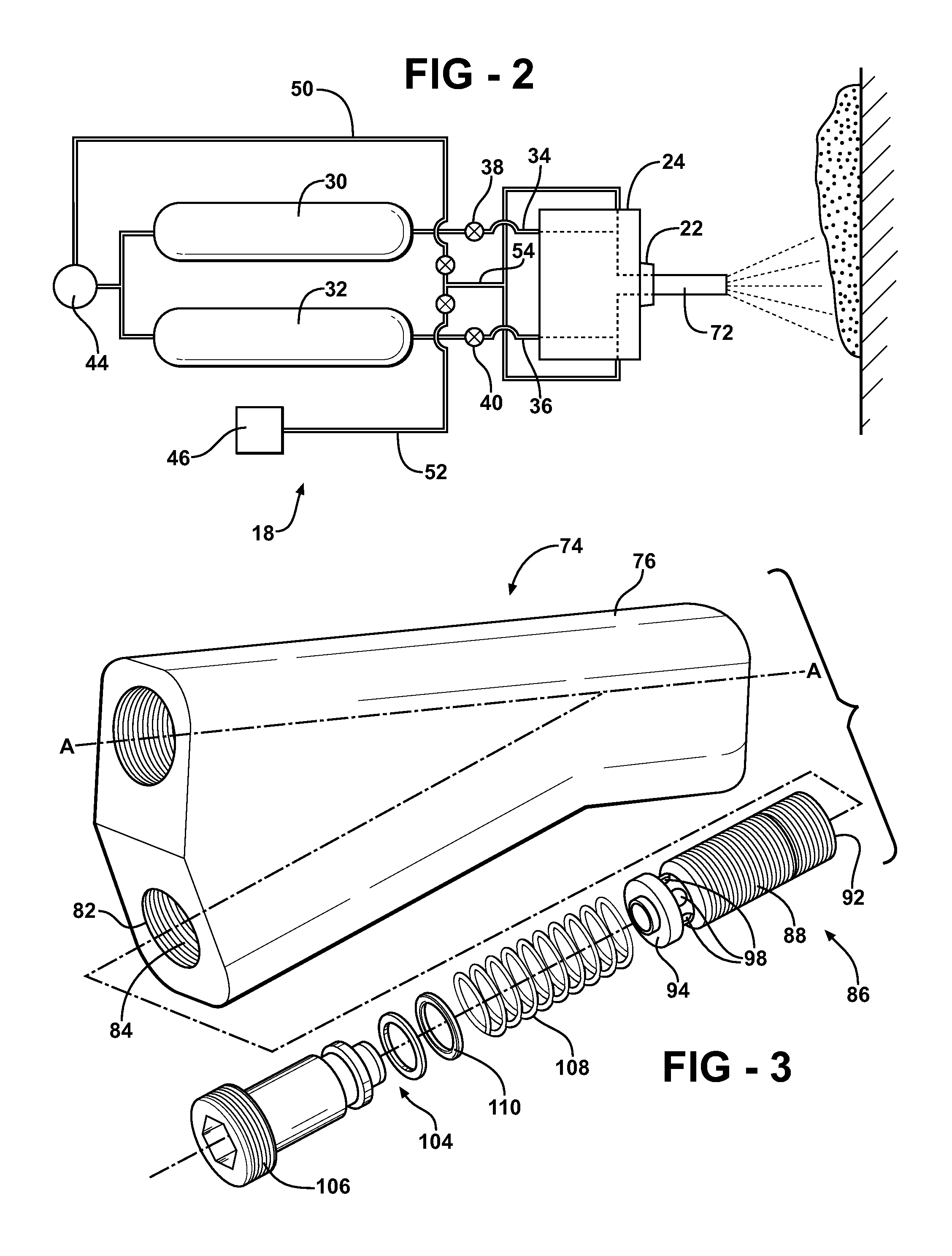
[0020]Referring to the Figures, wherein like numerals indicate like parts throughout the several views, a foam dispensing system 18 is generally shown. The foam dispensing system 18 is a two component system for handling a first component and a second component. The first component is typically a resin component and the second component is typically an isocyanate component. The foam dispensing system 18 mixes the resin and isocyanate components and dispenses the mixture therefrom, as shown in FIG. 2.

[0021]With respect to the polyurethane foam, the resin and isocyanate components are rapidly mixed together. A rapid cross-linking reaction and foam expansion commences, which ultimately yields the low density but relative high load bearing rigid polyurethane foam. The application of the polyurethane foam can, for example, be used for thermal insulation such as for appliances or buildings, marine floatation, coatings, and packaging. It is to be appreciated that the resin component and th...


PUM

PropertyMeasurementUnit
Pressureaaaaaaaaaa
Pressureaaaaaaaaaa
Flow rateaaaaaaaaaa

Abstract

A foam dispensing apparatus is capable of dispensing a mixture of a resin component and an isocyanate component. The foam dispensing apparatus includes a resin line and an isocyanate line connected to a manifold. A nozzle is connected to the manifold and the mixture is dispensed through the nozzle. The manifold defines a resin duct in communication with the resin line and the nozzle and an isocyanate duct in communication with the isocyanate line and the nozzle. At least one valve is connected to the resin and isocyanate lines and is moveable between an open position allowing flow through the resin and isocyanate lines and a closed position preventing flow through the resin and isocyanate lines. The valve is disposed exterior to the manifold and the flow is unregulated in the manifold for reducing maintenance of the manifold.

Description

CROSS-REFERENCE TO RELATED APPLICATIONS[0001]The subject patent application claims priority to and all the benefits of U.S. Provisional Patent Application Ser. No. 61 / 263,718 which was filed on Nov. 23, 2009, the entire specification of which is expressly incorporated herein by reference.BACKGROUND OF THE INVENTION[0002]1. Field of the Invention[0003]The subject invention generally relates to a foam dispensing apparatus and more particularly a foam dispensing apparatus for dispensing a mixture of a resin component and an isocyanate component.[0004]2. Description of the Related Art[0005]Chemical foam compositions, such as polyurethane foams, are presently well known and used in a number of different applications. Polyurethane foams are useful in such applications as thermal insulation, marine floatation, coatings, and packaging. Polyurethane foams are formed by the mixture of a resin component and an isocyanate component.[0006]The resin component and the isocyanate component are sepa...

Claims


Application Information

Patent Timeline
IPC IPC(8): B67D7/06
CPCB05B7/0025B05B7/0408B05B7/12B05B12/004B29B7/803B05B15/025B05B15/0266B29B7/7447B05B12/02B05B15/55B05B15/557B29B7/7409B29B7/7419B29B7/761B29B7/7615B29B7/74B05B7/04
Inventor SWAB, JOHN H.DUNLAP, MATTHEW C.ROWAND, WILLIAM
Owner BASF AG
Why Eureka
Try Eureka