Dental retention systems

a technology of dental retention and dentition, applied in the field of dental retention systems, can solve the problems of poor aesthetic appearance of the patient's dentition, low tolerance for mistakes, crown chipping, etc., and achieve the effect of effectively preventing relative movemen

Active Publication Date: 2011-05-26
RODO MEDICAL
View PDF13 Cites 12 Cited by
  • Summary
  • Abstract
  • Description
  • Claims
  • Application Information

AI Technical Summary

Benefits of technology

[0015]Once the crown has been desirably positioned upon the abutment assembly, the energy may be removed or ceased such that straightened arcuate portions of the elements reconfigure into their arcuate shape. As the arcuate portions reform, the elements may shorten in length thus retracting the upper retaining plate and radially expanding the arcuate portions into the widened diameter of the crown. The reconfigured arcuate portions compress the elements against the widened diameter thereby effectively preventing relative movement between the crown and the elements and locking the crown into position along the abutment.

Problems solved by technology

However, while utilizing cement to attach the crown to the abutment initially allows for aligning the crown more naturally with the dentition of the patient, the tolerance for mistakes is low once the cement has set because of the difficulty and expense in removing a cemented crown from the abutment.
Screw-type retention devices may also provide for good securement of the crown to the abutment, but occlusal contact within the patient dentition is often misaligned resulting in a variety of complications.
For instance, misaligned crowns result in a compromised occlusal table which in turn may lead to chipping of the crowns as well as poor aesthetic appearance of the patient's dentition.
However, such a device fails to disclose the use of shape memory materials utilized in the interaction between the abutment and the crown or bridge itself, as described in further detail below, as such an interaction facilitates the retention and retrieval of the crown or bridge from the abutment and / or implant.

Method used


Image

  • Dental retention systems
  • Dental retention systems
  • Dental retention systems

Examples


Embodiment Construction

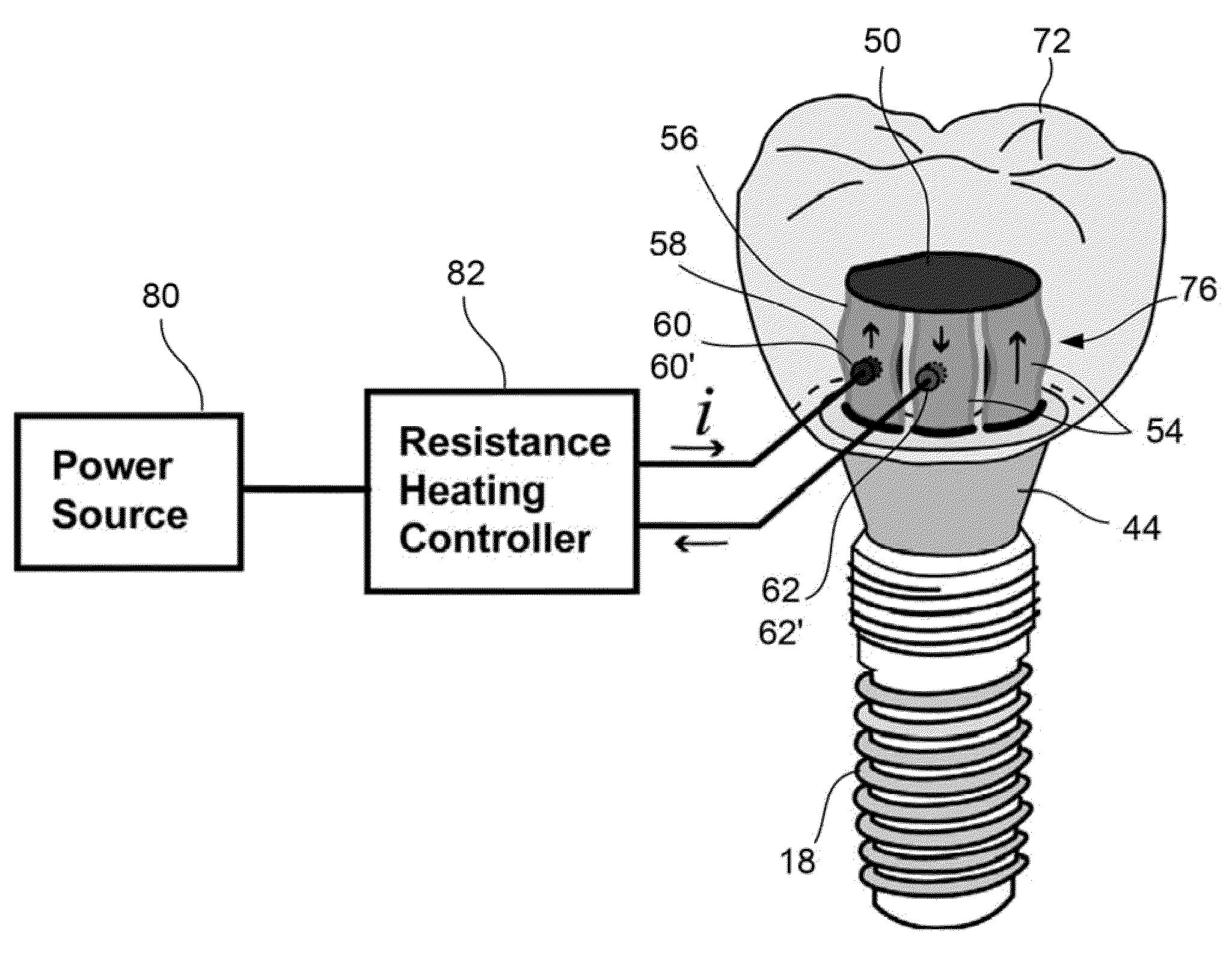
[0042]In positioning and securing an oral appliance, such as a crown or bridge, within the mouth of a patient, the retaining assemblies described herein allow not only for secure attachment but also for adjustment of the crown or bridge along the patient's dentition. The assemblies described also provide for mechanisms and methods to facilitate the entire removal of the crown or bridge from the abutment. In utilizing the abutment assemblies described herein, any number of typical anchoring implants may be bored into the bones within the mouth of the patient to provide for the structural support of the abutment assembly. Moreover, the implants and abutment assemblies described herein may be utilized in any number of locations within the mouth of the patient, for instance, along the maxilla or mandible or other locations within the body which may benefit from an adjustable abutment assembly as described herein.

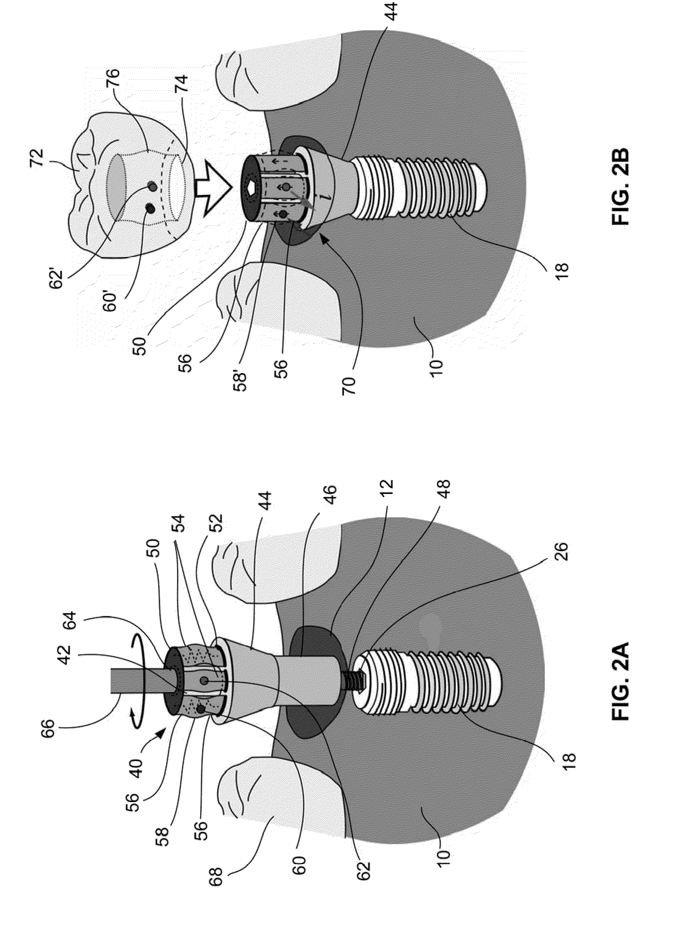
[0043]Turning now to FIG. 2A, one example of an abutment retaining assembly...


PUM


Abstract

Dental retention systems which facilitate the adjustment or removal of an oral appliance, e.g., a crown or bridge, from a reconfigurable abutment assembly are described. The adjustable abutment assembly may be secured to an anchoring implant bored into the bones within the mouth. The abutment assembly has a projecting abutment portion with one or more shape memory alloy compression plates or elements extending along the projecting abutment portion. Each of the plates has a length with one or more straightened portions and with at least one curved or arcuate portion. Energy may be applied to the elements such that the arcuate portion self-flattens to allow for the oral appliance to be placed thereupon while removal of the energy allows the elements to reconfigure into its curved configuration thereby locking the oral appliance to the abutment. Removal of the oral appliance may be effected by reapplication of energy to the elements.

Description

CROSS-REFERENCE TO RELATED APPLICATIONS[0001]This application is a continuation of U.S. patent application Ser. No. 12 / 504,561 filed Jul. 16, 2009, which is incorporated herein by reference in its entirety.FIELD OF THE INVENTION[0002]The present invention relates to methods and apparatus for retaining one or more dental prostheses in a mouth of a user. More particularly, the present invention relates to methods and apparatus for retaining one or more dental prostheses in a manner which facilitates placement and removal via an actuation mechanism from an anchoring implant and / or abutment.BACKGROUND OF THE INVENTION[0003]The use of dental prostheses to replace missing or damaged teeth is commonplace. Typically, artificial roots, or implants, are implanted into the bone of the patient's jaw and are used to provide structural support to an intermediate abutment. One or more artificial replacement teeth or crowns are then fastened to the abutment typically by cements or screws.[0004]FIGS...

Claims


Application Information

Patent Timeline
Patent Type & Authority Applications(United States)
IPC IPC(8): A61C3/00A61C8/00
CPCA61C8/0075A61C8/0062A61C8/0048A61C8/005A61C2201/007A61C8/0065A61C8/0066A61C13/235A61C8/0089
Inventor SEO, YOUNG
Owner RODO MEDICAL
Why Eureka
Try Eureka