Rotation-Rate Sensor Having A Quadrature Compensation Pattern

a quadrature compensation and rotation-rate sensor technology, applied in the field of rotation-rate sensors, to achieve the effect of less surfa

Active Publication Date: 2011-06-02
ROBERT BOSCH GMBH
View PDF12 Cites 7 Cited by
  • Summary
  • Abstract
  • Description
  • Claims
  • Application Information

AI Technical Summary

Benefits of technology

[0004]The example quadrature compensation pattern according to the present invention is advantageously suitable for quadrature compensation (resulting in forces fa,b,c). In addition, it also has two further advantages. The example quadrature compensation pattern according to the present invention does no

Problems solved by technology

One disadvantage of the related art is the fact that the quadrature compensation forces exert a resulting torque on the Coriolis frame about the z axis since, based on th

Method used


Image

  • Rotation-Rate Sensor Having A Quadrature Compensation Pattern
  • Rotation-Rate Sensor Having A Quadrature Compensation Pattern
  • Rotation-Rate Sensor Having A Quadrature Compensation Pattern

Examples


Embodiment Construction

[0010]The related art as well as exemplary embodiments of the present invention are shown in the figures and are described below.

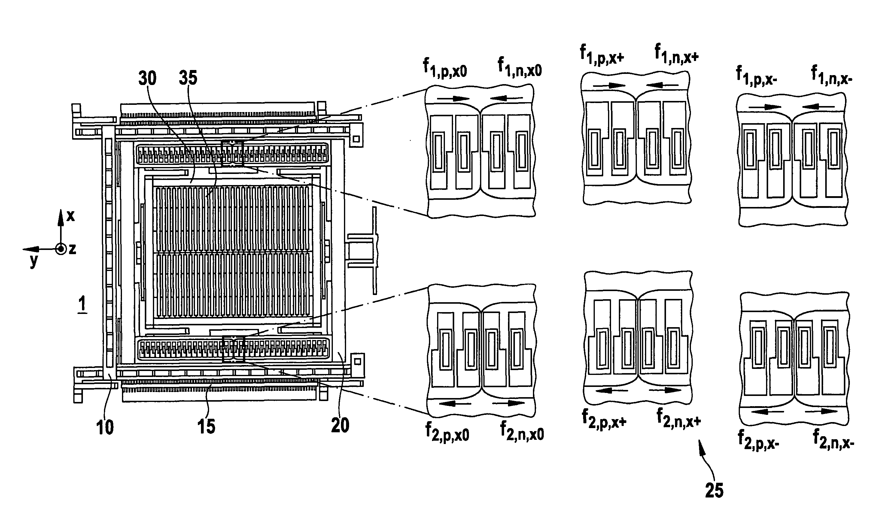
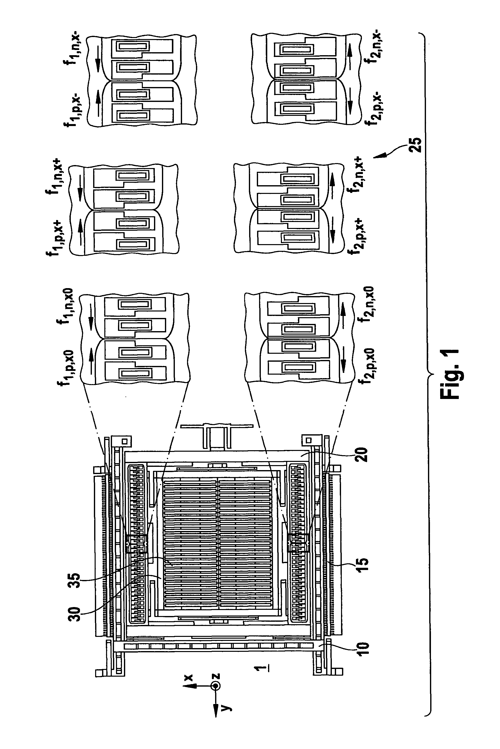
[0011]FIG. 1 shows a conventional rotation-rate sensor having quadrature compensation patterns as described in German Patent Application No. DE 10237411 A1. What is shown is one-half of a micromechanical pattern of a rotation-rate sensor. What is shown is a drive frame 10 having drive vibration patterns 15, a Coriolis frame 20 situated in it having quadrature compensation patterns 25 and a detection frame 30 situated in it that has detection electrodes 35. Drive frame 10 is suspended on substrate 1, situated below it, with springs, using an anchoring arrangement in such a way that the driving mass can preferably execute only one in-plane motion (parallel to the plane of the substrate) in a first direction, or rather, according to a first axis (the x axis), and an in-plane motion in a second axis (the y axis), which is perpendicular to the first axis, is su...


PUM


Abstract

A rotation-rate sensor having at least one quadrature compensation pattern, which includes at least one first electrode and one second electrode. The second electrode has a first electrode surface and a second electrode surface which are situated opposite to each other. The first electrode is situated in an intermediate space, between the first electrode surface and the second electrode surface. The first electrode surface and also the second electrode surface, over their extension, are at a different distance from the first electrode. The first electrode surface and the second electrode surface of the second electrode are at generally the same distance from each other, over their extension.

Description

FIELD OF THE INVENTION[0001]The present invention relates to a rotation-rate sensor having at least one quadrature compensation pattern, which includes at least one first electrode and one second electrode. The second electrode has a first electrode surface and a second electrode surface which are situated opposite to each other, in this context. The first electrode is situated in an intermediate space between the first electrode surface and the second electrode surface. The first electrode surface or even the second electrode surface, over their extension, have a different distance from the first electrode.BACKGROUND INFORMATION[0002]During operation, rotation-rate sensors have a drive vibration, in order to detect a deflection when a rotational motion occurs as a result of a Coriolis force. As a result of manufacturing tolerances, cross feed of the drive motion to the detection motion of the sensor patterns may occur in micromechanical rotation-rate sensors. For this reason, so-ca...

Claims


Application Information

Patent Timeline
IPC IPC(8): G01C19/56
CPCG01C19/5762
Inventor NEUL, REINHARD
Owner ROBERT BOSCH GMBH
Why Eureka
Try Eureka