Dual ultrasonic train detector

a detector and ultrasonic technology, applied in the direction of railway components, railway signalling, railway signalling and safety, etc., can solve the problems of dual sensor redundancy and incorrect identification of running rails

Active Publication Date: 2011-06-02
HARSCO CORP
View PDF15 Cites 14 Cited by
  • Summary
  • Abstract
  • Description
  • Claims
  • Application Information

AI Technical Summary

Benefits of technology

[0008]It is an object of the present invention to provide an improved portable train detector (PTD) and method over those used in the prior art for warning workers, railroad personnel and others of an oncoming train so that they can safely get off the tracks. This invention also alerts the operator of an approaching train of the presence of other train(s), workers, railroad personnel and others, such as track walkers and the like on the track. The PTD detects the presence of a passing train and sends a secured wireless signal to workers that are wearing personal armband devices and / or sends such signals to activate portable warning lights and / or horns in the work zone. The PTD includes first and second ultrasonic transducers mounted 10 inches apart and facing the track and train wheels. The dual ultrasonic transducers of this invention are also herein referred to as activation sensors, and they not only detect the movement of an approaching train but also the direction and speed of the train up to 170 mph. The dual ultrasonic train detector of this invention further includes an embodiment that can be used in single track operations where the train movement can be in either direction on one track. The dual ultrasonic train detector of this invention transmits and receives sonic energy within a 20-inch maximum sensing range. The train detector operates on 12 to 24 VDC and employs piezoelectric materials to produce such sonic energy with microprocessors to aid in the computations necessary to obtain the desired information, as described below. The sensors used in this invention detect only the designated objects through a “window” and are designed to ignore other surrounding sonic information which might otherwise interfere with the signal. Each sensor of this invention can be adjusted within the sensing window between a near and far limit and can be set anywhere within the sensing range between 20 inches to as little as 0.25 inch. Each sensor can be equipped with a two-color status LED to show the state of output. When the output is active, the LED can be amber; and when the output is inactive, the LED is green. Thus the LED serves to show the sensing status of the sensor. During operation the sensor continually measures the elapsed time from the first pulse's reflected echo received after a pulse transmission. This transmitted pulse starts a clock to register the elapsed time to the first pulse echo received. The microprocessor calculates the distance the sonic signal has traveled out to the wheel of the train along with the time the signal travels back to the sensor using the formula: D−T Vs / 2 where D=the distance from the sensor to the train; T=the elapsed time between the pulse transmission and its first received echo; and Vs=the velocity of sound which is approximately 1100 ft / sec. During operation the calculated distance D between the sensor and the train is compared to the distances associated with the window limits. Once the detection unit of this invention is secured in place adjacent to the track and the activation key is turned to the “on” position, the dual sensors accurately measure the elapsed time from the first pulse echo received after each pulse transmission and determine whether the window is clear of any movement or object detection. If the detection unit is removed while the key is still in the “on” position, the elapsed time from the first pulse echo received after each pulse transmission determines that the window has changed and that such movement is thus detected and will activate and send a disruption signal to the microprocessor. Thus such sonic signals can also indicate the detector's removal from a location which feature aids in its timely replacement, if stolen. The dual ultrasonic train detector can be positioned perpendicularly to the track a distance 0.25-20 inches therefrom and is positioned no higher than the running rail. It is important that when spacing the detector between 0.25-20 inches from the track that the detector be positioned no higher than the running rails of the train so that the detector will be within non-fouling areas of the train to avoid having the train strike and damage the detector. Further, since the detector of this invention senses both metallic and nonmetallic objects, it is important to be able to adjust the distance of activation so that the ultrasonic sensors will only detect and activate the detector when a train moves through the area of sensing. By having two redundant sensors, the device of this invention can verify that the object is a large mass, such as a train wheel, which will cause the device's activation and can distinguish such large mass from smaller masses, such as a person walking too close to the detector to prevent the detector's activation. Further, the dual sensor redundancy acts to only activate when there is a train on the track that the device is affixed to and not when there is a train on an adjacent track. The ultrasonic sensors are aimed at a 45 degree angle upwards from the horizontal plane of the track rail so as to sense the train's wheels on the rail. If the sensors are not set at such 45 degree angle, they may incorrectly identify the running rail as the large object that the sensor is trying to detect. By having the sensors aimed at a 45 degree angle, it ensures that the sensors will “see” over the running rail and activate based only on the pattern being the train's wheel sensed within the 0.25-20 inch range. Generally the dual ultrasonic sensors can be placed within a single housing spaced 10 inches apart from one another which distance allows enough space apart to measure time and distance from one sensor's activation to the other which information is utilized by the microprocessor which has a programmed algorithm to determine the train's speed and direction. In a preferred embodiment the sensors can be disposed under a protective guard a distance of about 0.25-20 inches from the rail so as to detect movement of the wheels of a passing train on the rail. By using thin 1 / 10 inch diameter waves, the ultrasonic sensors can sense the train's travel direction when the train wheel passes between the first ultrasonic sensor and the second ultrasonic sensor. Further, by using such 1 / 10 inch diameter waves and determining the time of activation, the device can then determine not only the direction, but also the speed of the passing train. When a train's wheel passes the first sensor, the sensor sends a signal to the microprocessor which logs the time of the signal. When the same wheel then passes the second sensor, that sensor sends a signal to the microprocessor which also logs the time. The microprocessor can then determine how long it took between the activation of the first sensor and the second sensor. By knowing that both sensors are 10 inches apart, the microprocessor can determine the speed of the train at the point that it passed the detector. Also, since the microprocessor records when each of the dual sensors was activated, it can determine which sensor was activated first and utilize the second sensor to verify the activation, therefore determining the direction of travel of the train. This feature allows the dual ultrasonic sensors to be placed adjacent to a track having single track operation thereon, and the dual ultrasonic sensor train detector can, for example in one embodiment, be set to activate when a train enters the work zone but not when the train exits the work zone. The device of this invention can be attached on either rail of a track on either the inside or outside of such rail. By providing for the ultrasonic sensors to have a wave sensing distance of between 0.25-20 inches at a 45 degree angle from a horizontal plane, it allows the activation of the ultrasonic sensors only by the trains traveling on the track on which the device of this invention is installed and prevents activation of the device by trains on adjacent tracks. Further, by using the wave sensing distance of between 0.25-20 inches at such 45 degree angle, the device can be set to activate in inclement weather, if desired, such as in heavy snow or heavy rain. Such heavy rain or heavy snow can cause a signal pulse echo to be received after each pulse transmission.
[0009]The dual ultrasonic train detector of this invention is mounted on a mounting plate adapted to fit between two railroad ties with slots to allow for sliding of the device's housing back and forth under the rail for adjustments before being tightened in place. The tightening clamps can also be utilized in conjunction with different size running rails. The mounting system of this invention can further be utilized between both traditional rail ties and concrete ties and can be adapted for three different size running rail heights. Due to the low profile of the device of this invention, it is generally disposed below the running rail top height with its low profile housing not being higher than the height of the running rail to allow for an easy fit on or beside any track without becoming an obstruction to any object, such as the train that is higher than the top of the running rail.
[0010]It is a further goal of this invention that the weight of the dual ultrasonic train detector be under 10 lb. for easy carrying and installation.

Problems solved by technology

Further, the dual sensor redundancy acts to only activate when there is a train on the track that the device is affixed to and not when there is a train on an adjacent track.
If the sensors are not set at such 45 degree angle, they may incorrectly identify the running rail as the large object that the sensor is trying to detect.

Method used


Image

  • Dual ultrasonic train detector
  • Dual ultrasonic train detector
  • Dual ultrasonic train detector

Examples


Embodiment Construction

)

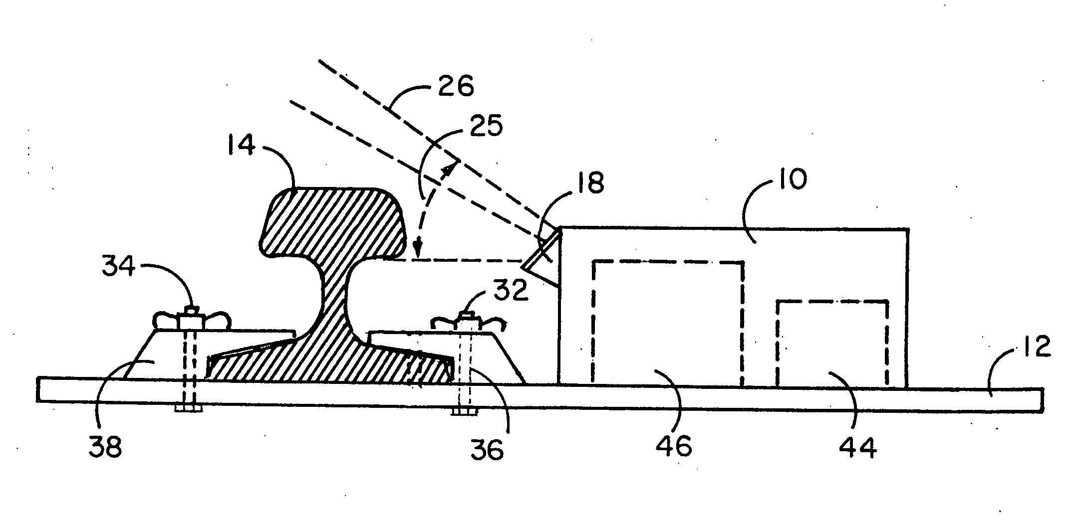
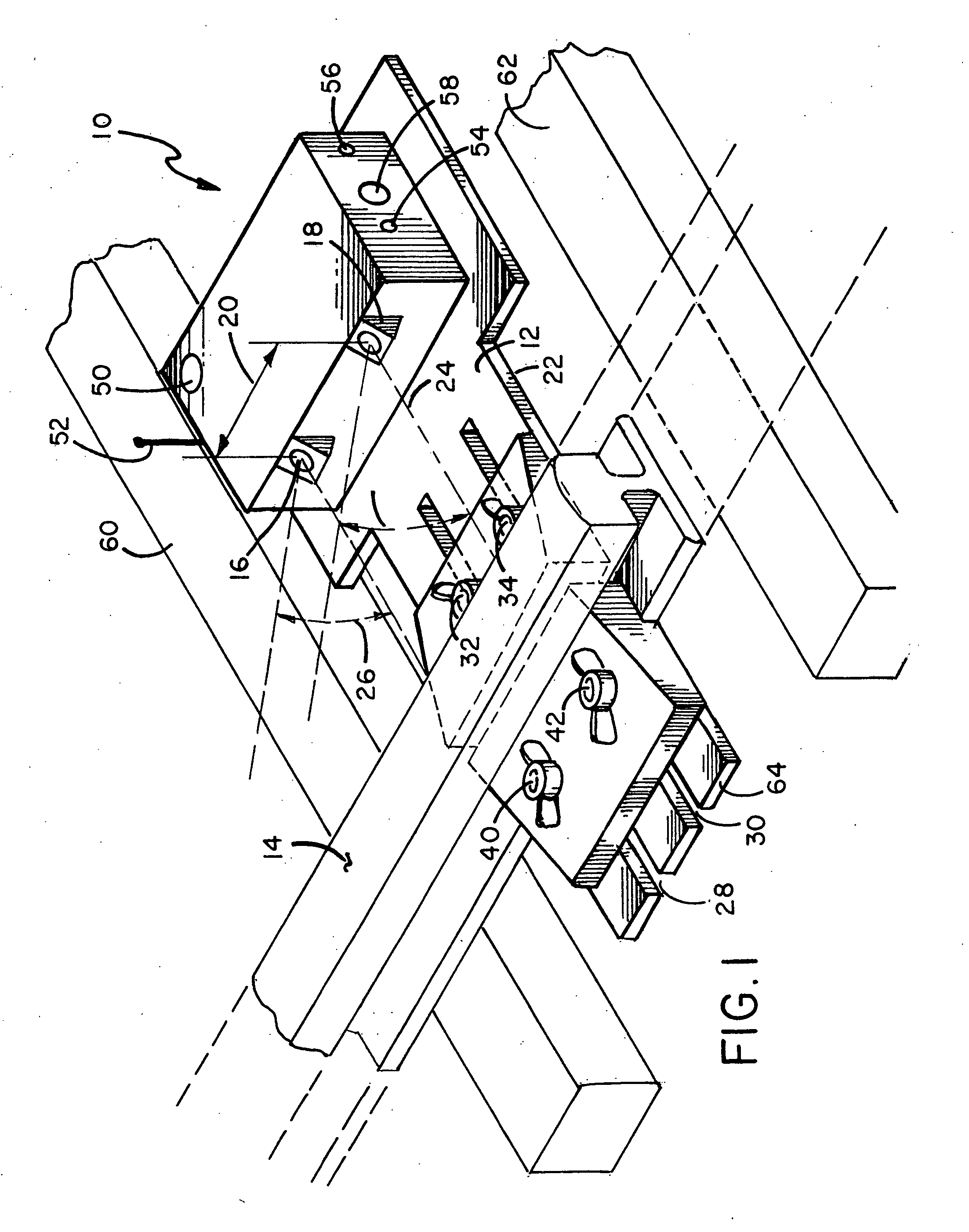
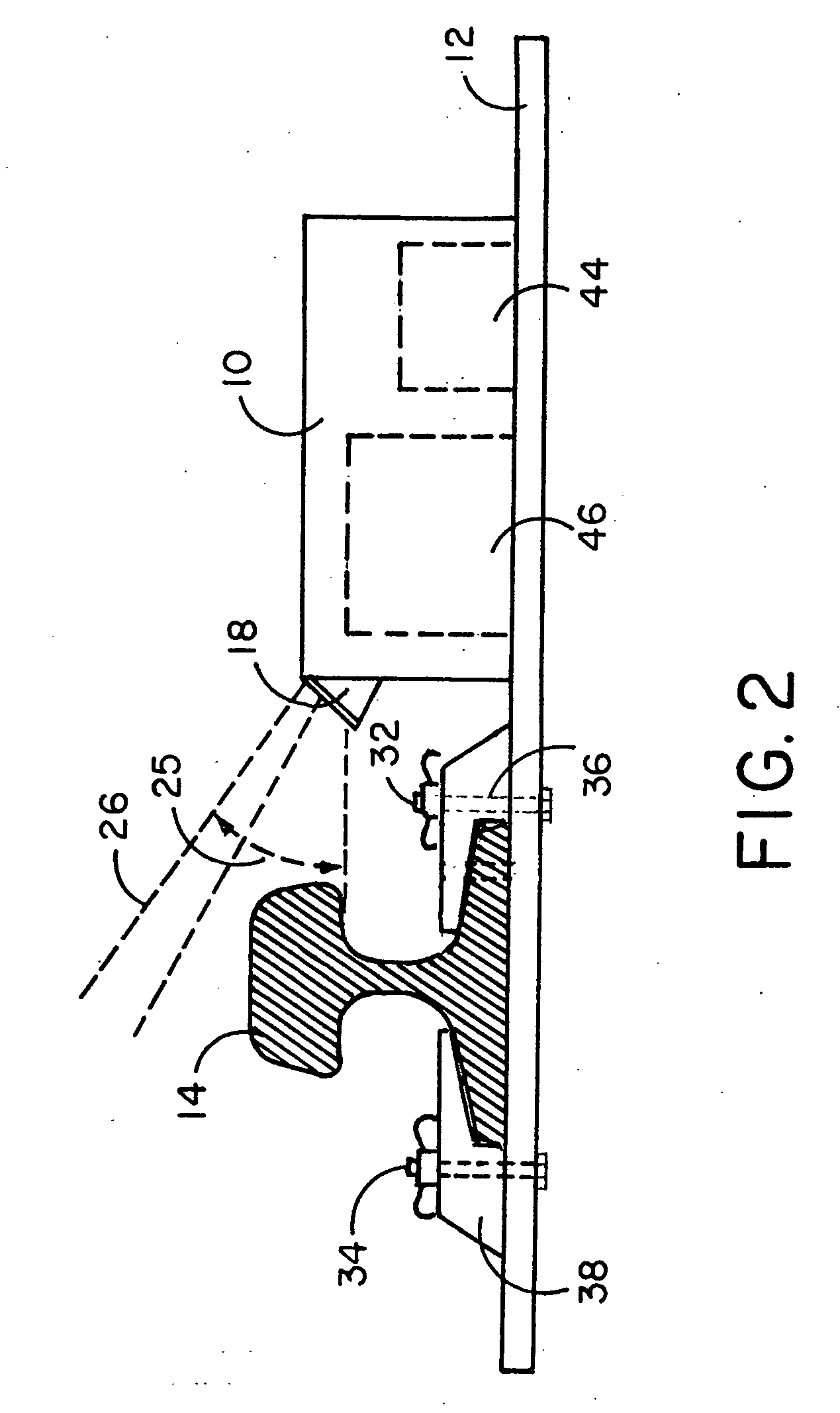
[0013]FIG. 1 illustrates a perspective view of portable train detector 10 of this invention mounted on mounting plate 12. Within mounting plate 12 are defined two parallel elongated first and second slots 28 and 30 which extend to end 64 of mounting plate 12. Mounting plate 12 can be made of a nonconductive material, and it extends under track 14 between first tie 60 and second tie 62. The mounting plate is disposed immediately under the track and clamped thereto to position the portable train detector 10 a selected distance 22 from track 14. When portable train detector 10 is at the desired distance in the range between 0.25-20 inches from track 14, first clamp 36 and second clamp 38, as seen in FIG. 2, are attached, respectively, by first and second bolts 32 and 34, extending through first and second slots 28 and 30, respectively, against one side of the base of track 14 with the second clamp 38 affixed by third and fourth bolts 40 and 42, also passing through first and second sl...


PUM


Abstract

A train detector having dual ultrasonic sensors positioned adjacent to a rail for sensing the movement thereby of a train wheel and determining the direction and speed of the train for transmitting such information to nearby workers and signal devices and a method of train detecting are disclosed.

Description

BACKGROUND OF THE INVENTION[0001]1. Field of the Invention[0002]The device and method of this invention reside in the field of railroad warning systems for train operators, railroad personnel and others working in the vicinity of railroad tracks to give train operators warning of railroad personnel near the train tracks and to give train workers, railroad personnel and others warning of oncoming trains, and more particularly relate to a portable train detector and method of detecting a train on a train track.[0003]2. Description of the Prior Art[0004]In the fields of light rail vehicles, trolley lines, third rail-powered vehicles and tramways, alerting work crews or railroad personnel on or near the tracks of an oncoming train or vehicle, herein referred to as a “train,” has been addressed by many methods. Since working on tracks can involve work methods such as digging, hammering and other loud-noise producing acts, workers frequently cannot hear oncoming trains and are in great da...

Claims


Application Information

Patent Timeline
Patent Type & Authority Applications(United States)
IPC IPC(8): B61L25/02
CPCB61L1/02B61L1/165B61L25/023B61L25/021B61L23/06
Inventor BARTEK, PETER M.
Owner HARSCO CORP
Why Eureka
Try Eureka