

Stack of folded material
a technology of folded materials and stacks, applied in the field of stacks of folded materials, can solve the problems of inability to determine characteristics, affect the total visual appearance of stacks, and increase manufacturing costs, and achieve the effect of being easily identifiabl
- Summary
- Abstract
- Description
- Claims
- Application Information
AI Technical Summary
Benefits of technology
Problems solved by technology
Method used
Image

Examples
first embodiment
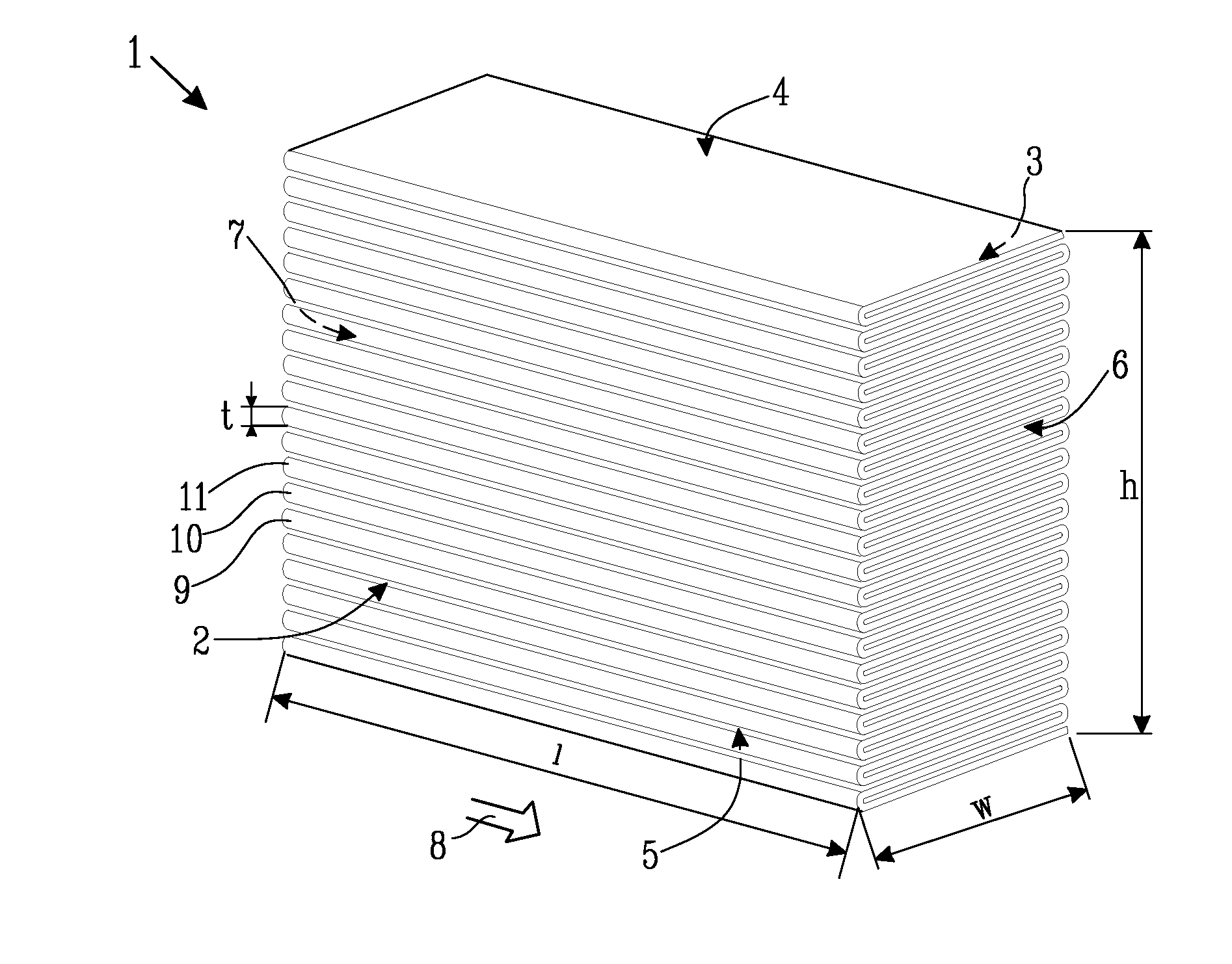
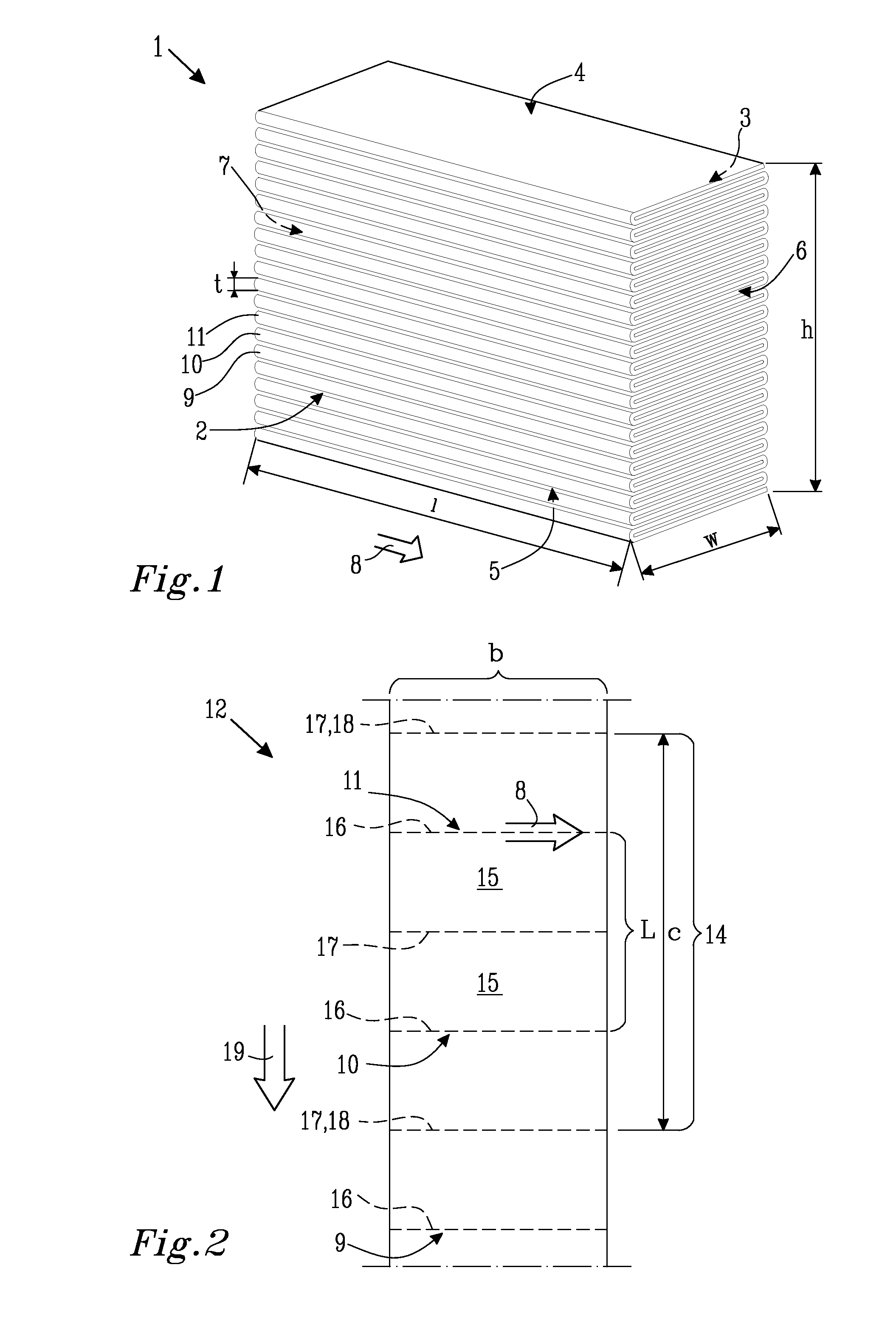
[0053]FIGS. 1 to 4 illustrate the general principle of construction of a stack of a folded web-shaped material, while FIGS. 5 and 6 show a first embodiment according to the invention.
[0054]FIG. 1 shows an exemplary stack 1 formed from an intermediate web. The stack has two face sides, a first face side 2 facing forward in FIG. 1, and a second face side 3 opposite to the first face side 2. The stack further has a top side 4, a bottom side 5, a first end side 6, and a second end side 7 opposing the first end side 6. An edge direction, depicted by arrow 8, is defined as the direction which is in the plane of the first face side 2 and parallel to the top side 4. The first face side 2 comprises a first plurality of edge portions 9, 10, 11 formed by a first set of folds in the intermediate web and the second face side 3 comprises a second plurality of edge portions formed by a second set of folds in the intermediate web. Each such edge portion has a thickness t which normally corresponds ...
second embodiment
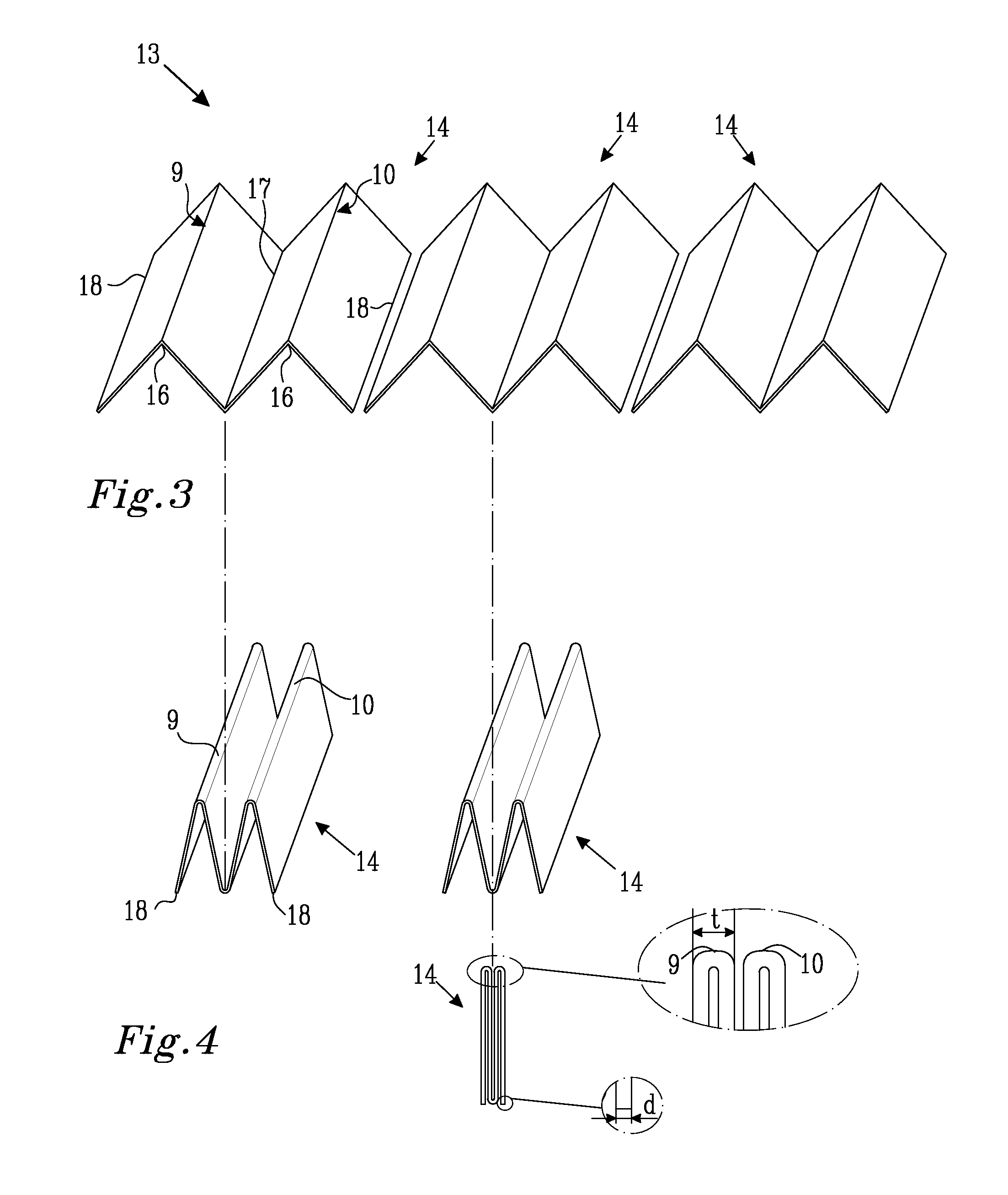
[0100]FIGS. 10 and 11 show a second embodiment, wherein the intermediate web 13 of FIG. 10 comprises two web-shaped materials, a first web-shaped material 12 and a second web-shaped material 23, which are interfolded with each other. Individual sheets 14 can be separate or connected to the next sheet 14 in the same web-shaped material by a separation line. The web-shaped materials are positioned so that the sheets of one web-shaped material are partly overlapping with the sheets of the other web-shaped material, in this case by about half their lengths. The length of a sheet 14, denoted by c, is two panels. The sheets of the first web-shaped material 12 will form the edge portions 9, 10, 11 of one face side of the stack. The sheets of the second web-shaped material 23 will form the edge portions 24, 25 of the opposing face side of the stack. The distance L in the web extension direction along the first web-shaped material between adjacent folds of the same set of folds of the interm...
third embodiment
[0101]In FIG. 12 a third embodiment is illustrated, wherein the intermediate web 13 comprises two interfolded web-shaped materials 12, 23. The sheet length c is four panels and the sheets 14 are separated by separation lines 18. The distance L in the web extension direction along the web-shaped material between adjacent folds of the same set of folds of the intermediate web is in this case two panels. Two consecutive edge portions 9, 10 on the same face side are therefore located on the same sheet 14. When the intermediate web 13 is folded, one face side will have all the edge portions of the first web-shaped material 12 and the other face side will have all the edge portions of the second web-shaped material 23. Every second edge portion 24 of the second web-shaped material 23 will be located on a separation line. A stack formed from the intermediate web will have one face side where the second web-shaped material 23 is visible and which has a separation line at every second edge p...
PUM
| Property | Measurement | Unit |
|---|---|---|
| thickness | aaaaa | aaaaa |
| thickness | aaaaa | aaaaa |
| thickness | aaaaa | aaaaa |
Abstract
Description
Claims
Application Information