Steam mop with shuttling steam distributor

a steam distributor and mop technology, applied in the field of surface cleaners, can solve the problems of embedded dirt, dust, debris, etc., and achieve the effect of reducing the amount of dust, dust, and debris

Active Publication Date: 2011-06-09
BISSELL INC
View PDF2 Cites 29 Cited by
  • Summary
  • Abstract
  • Description
  • Claims
  • Application Information

AI Technical Summary

Problems solved by technology

During use, the mop pad eventually becomes saturated ...

Method used


Image

  • Steam mop with shuttling steam distributor
  • Steam mop with shuttling steam distributor
  • Steam mop with shuttling steam distributor

Examples


Embodiment Construction

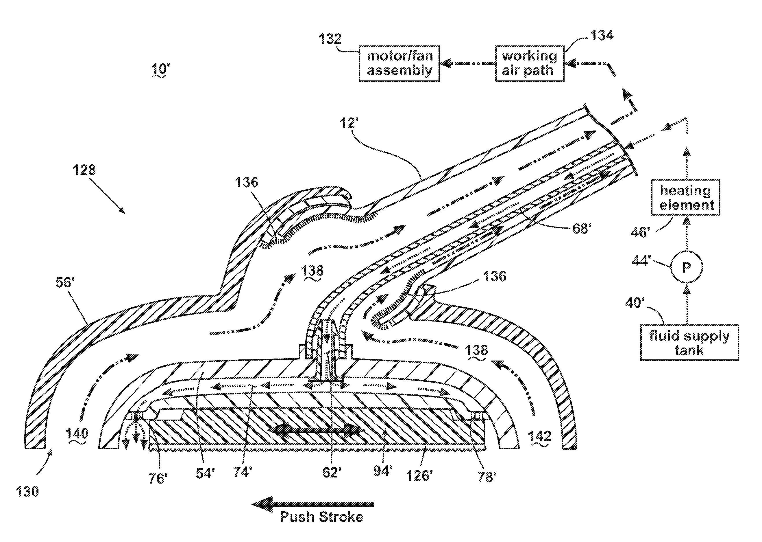
[0032]The invention relates to a surface cleaning apparatus that is capable of generating steam and applying that steam to the surface to be cleaned, which can include both carpeted and bare floor surfaces.

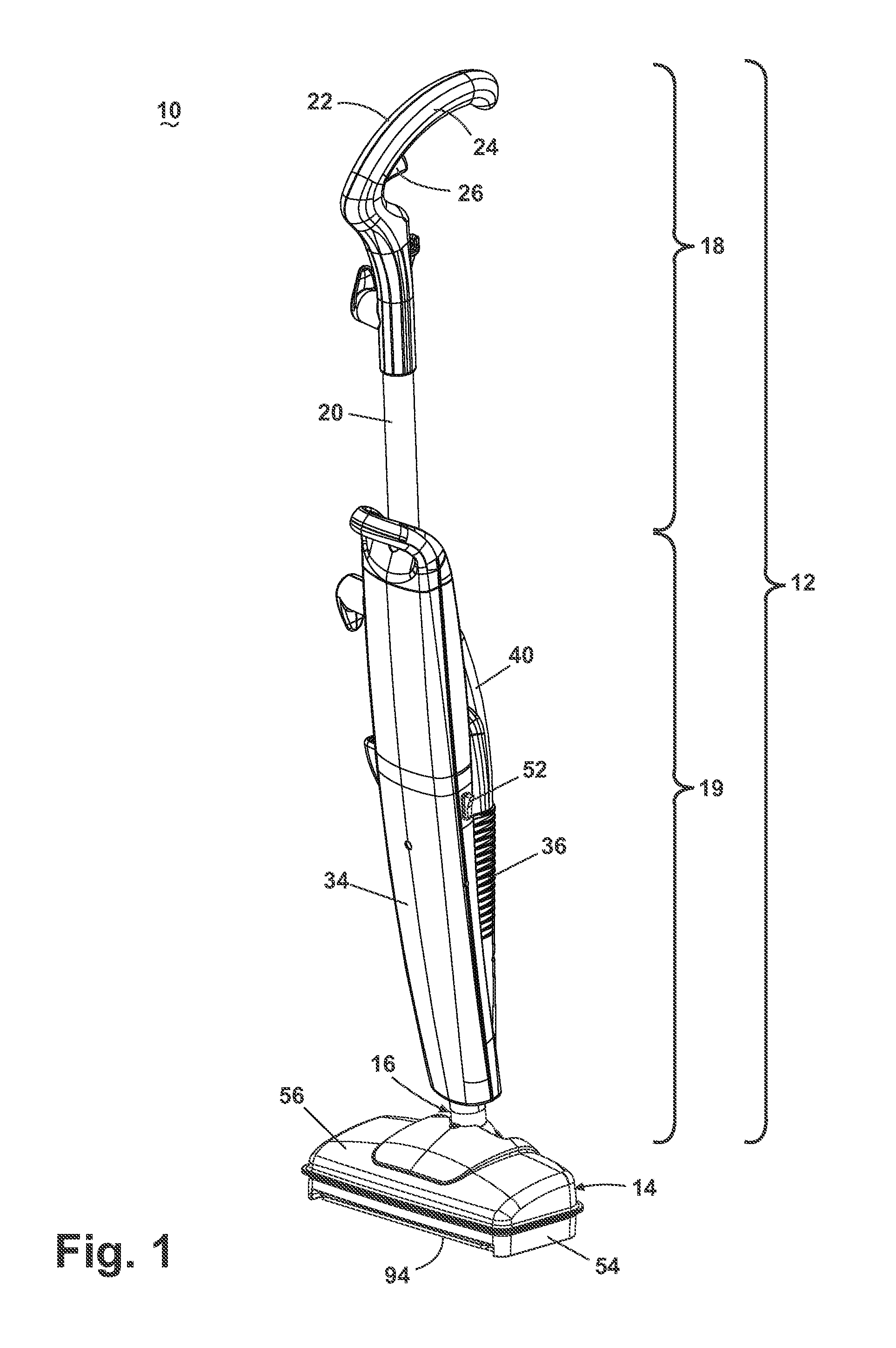
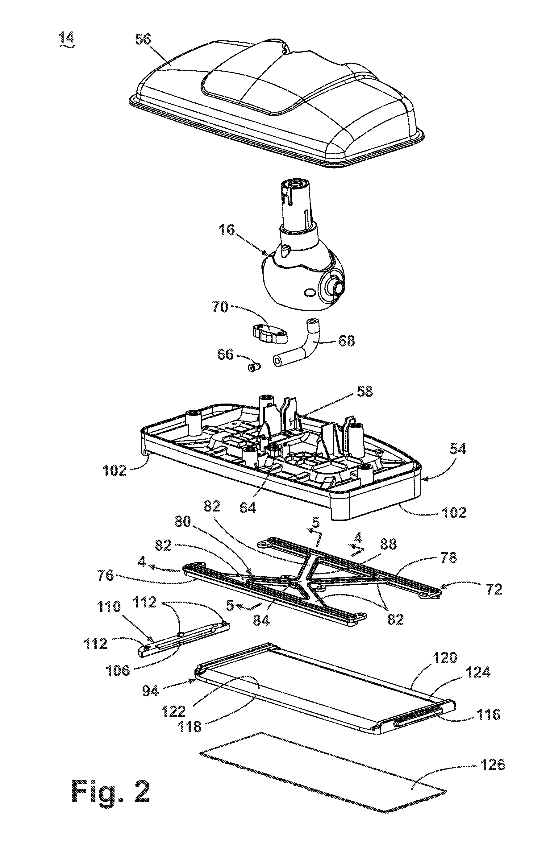
[0033]Referring to the drawings, and in particular to FIGS. 1-3, a steam mop 10 according to the invention for cleaning hard floor surfaces, such as tile, linoleum, and wood, comprises a housing with an upright handle assembly 12 and a foot 14 swivelably mounted to the handle via a conventional universal joint 16. The foot 14 is adapted to glide across a cleaning surface and the handle 12 is configured to direct the foot 14 across the cleaning surface. The universal joint 16 permits the foot 14 to swivel multi-axially relative to the upright handle assembly 12.

[0034]The upright handle assembly 12 further comprises an upper handle assembly 18 and a lower handle assembly 19. The upper handle assembly 18 comprises a handle tube 20 connected to a handle grip 22 that is engagable by a ...


PUM


Abstract

A surface cleaning apparatus, and in particular a steam mop, comprises a steam delivery system for generating and distributing steam onto a surface to be cleaned. The steam mop further comprises a handle assembly mounted to a foot assembly that has a shuttling plate slidably mounted beneath the foot assembly, wherein the shuttle plate is configured to selectively divert steam through one of a pair of steam distributors positioned at a forward and rearward portion of the foot assembly dependent on the cleaning stroke direction of the steam mop. In one embodiment, the surface cleaning apparatus further comprises a vacuum source mounted thereto and at least one suction nozzle connected to the vacuum source and adapted to contact the surface to be cleaned and to draw moisture and debris from the surface.

Description

CROSS-REFERENCE TO RELATED APPLICATION[0001]This application claims the benefit of U.S. Provisional Patent Application No. 61 / 266,285 filed Dec. 3, 2009, which is incorporated herein by reference in its entirety.BACKGROUND OF THE INVENTION[0002]1. Field of the Invention[0003]This invention relates to a surface cleaner. In one of its aspects, the invention relates to an upright bare floor steam cleaner. In another aspect, the invention relates to a bare surface cleaner that performs steam mopping. In another aspect, the invention relates to a steam cleaner configured to distribute steam at the leading edge of a steam pad on both forward and back strokes. In still another aspect, the invention relates to a bare surface cleaner that simultaneously performs steam mopping and vacuuming. In yet another aspect, the invention relates to a steam vacuum foot that selectively directs steam to a leading edge on both forward and back strokes while simultaneously applying continuous suction in fr...

Claims


Application Information

Patent Timeline
IPC IPC(8): A47L7/00
CPCA47L11/4036A47L11/4044A47L13/225A47L11/4088A47L11/4086A47L9/0483A47L11/34A47L11/40F22B1/28
Inventor KREBS, ALAN J.
Owner BISSELL INC
Why Eureka
Try Eureka