
Protector and wire harness

a protection and wire harness technology, applied in the direction of insulated conductors, cables, electric/fluid circuits, etc., can solve the problems of affecting the performance affecting the service life of the wire harness, so as to reduce the carrier space, reduce the load against the corrugated, and discharge easily

Active Publication Date: 2011-06-09
YAZAKI CORP
View PDF6 Cites 32 Cited by
  • Summary
  • Abstract
  • Description
  • Claims
  • Application Information

AI Technical Summary

Benefits of technology

[0021]According to the invention described in claim 1, protector, which can discharge water collected in the corrugated tube into an outside, can be provided.
[0022]According to the invention described in claim 2, it is possible to discharge the water into the outside more natural.
[0023]According to the invention described in claim 3, it is also possible to discharge the water. In addition, a wire harness which is possible to reduce carrier space can be provided.
[0024]According to the invention described in claim 4, a wire harness of low height can be provided.
[0025]According to the invention described in claim 5, it is possible to discharge water into the outside more natural.
[0026]According to the invention described in claim 6, the wire harness which can discharge easily and decrease load against the corrugated tube is provided.

Problems solved by technology

Since vehicle is used to under various environmental conditions, the above-mentioned prior art has the following problems.
As a result, there is a puddle in the collected place.
Thereby, if a high-voltage electrical wire is soaked in the puddle, the high-voltage electrical wire may be damaged.
So, the above-mentioned prior art has problems of water.
Further, since the metallic protection pipe is produced by bending work three-dimensionally, stereoscopic space is required.
That is, the above-mentioned prior art also has problem of space.

Method used


Image

  • Protector and wire harness
  • Protector and wire harness
  • Protector and wire harness

Examples


Embodiment Construction

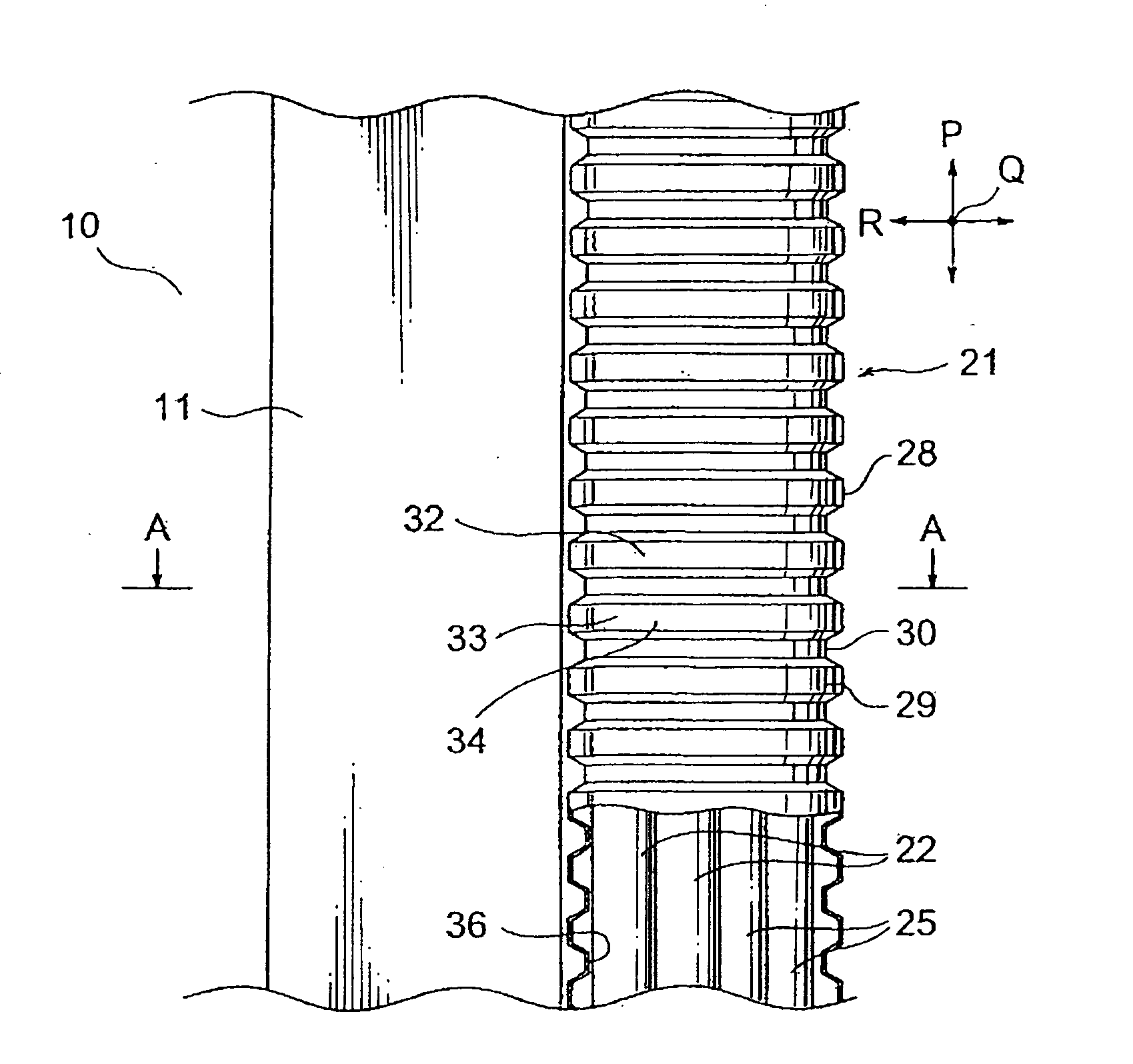
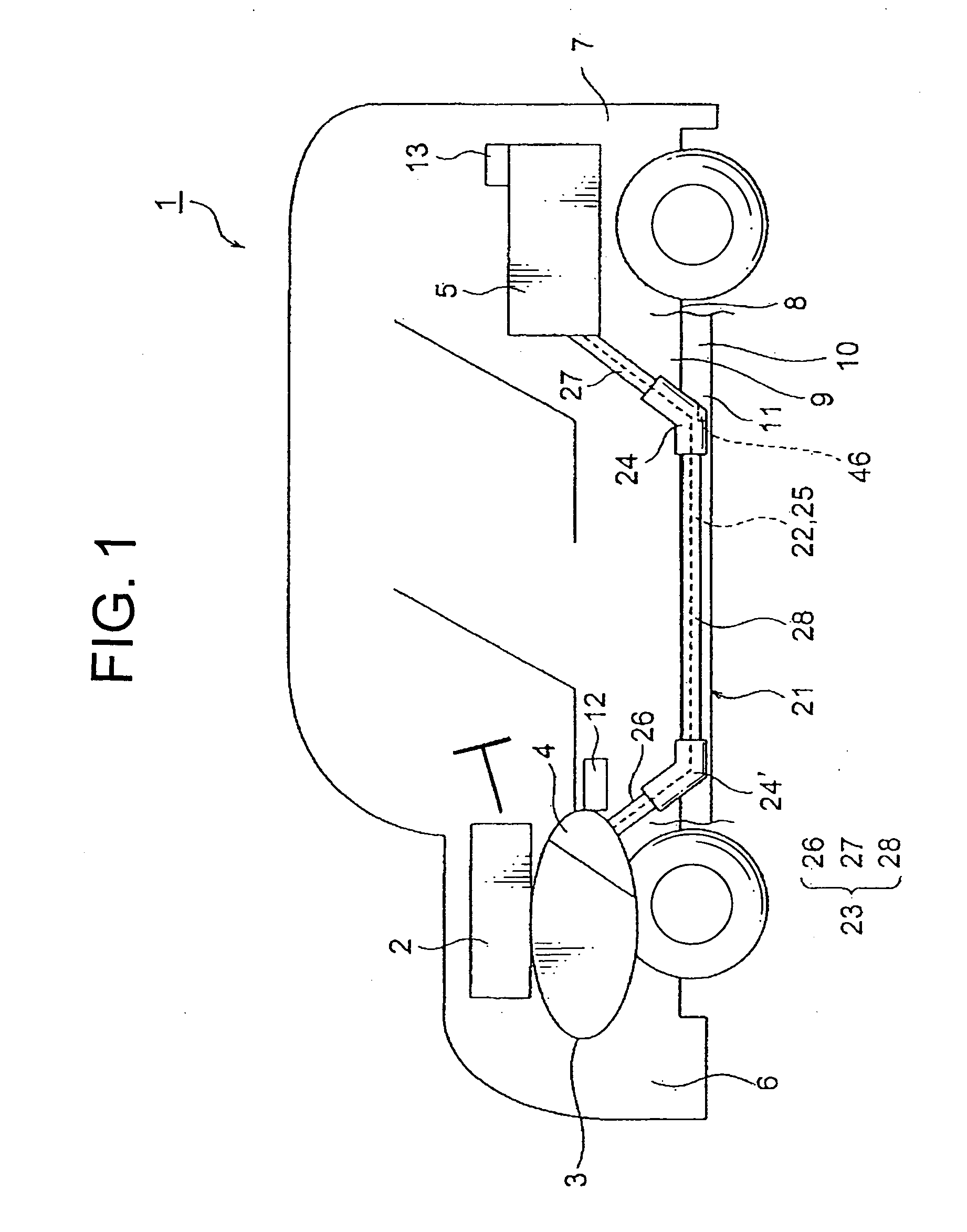
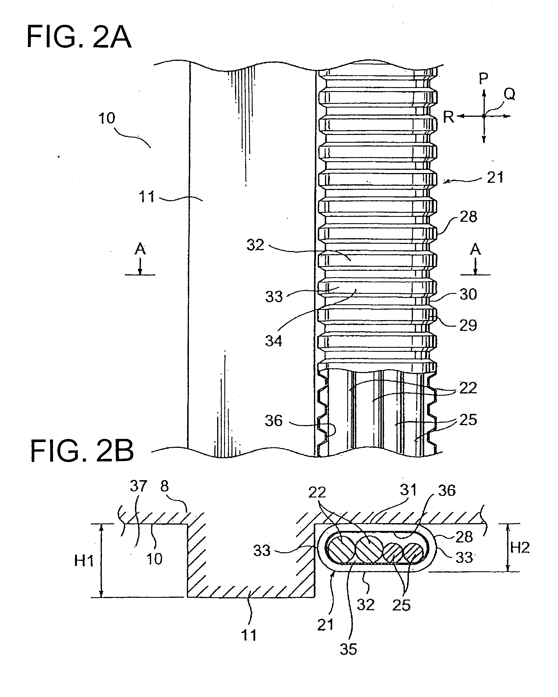
[0034]Hereinafter, the present invention will be explained with reference to FIGS. FIG. 1 is an exemplary configuration view showing an embodiment of a protector and a wire harness of the present invention. Furthermore, FIG. 2 is a view showing a body under floor protection member and a lean hose. FIG. 2A is an essential enlarged view (including part of cross section) when the body under floor is seen from the ground. FIG. 2B is a cross-sectional view taken along the line A-A in FIG. 2A.

[0035]Also, FIG. 3 is a perspective view of the protector of the present invention. FIG. 4 is a perspective view of the protector body in the protector of the present invention. FIG. 5 is a perspective view of drainage hole seeing from an inside of the protector body. FIG. 6 is a perspective view of the drainage hole seeing from an outside of the protector body.

[0036]Furthermore, FIG. 7 is an exemplary view showing process from manufacture of the wire harness to vehicle assembly. FIG. 7A is a view of...


PUM

PropertyMeasurementUnit
shapeaaaaaaaaaa
voltageaaaaaaaaaa
stiffnessaaaaaaaaaa

Abstract

[Problem] To provide a protector capable of discharging water into an outside and a wire harness including the protector[Means for Solving Problem] A drainage hole 46 is formed as a portion so as to discharge water collecting in an electrical wire receiving portion 45 into an outside. The drainage hole 46 is formed so as to penetrate through the electrical wire receiving portion 45 and toward the rear of a vehicle. Further, the drainage hole 46 is formed so as to gradually slope from the electrical wire receiving portion 45 toward the ground surface. The drainage hole 46 is a through hole which is formed at a position near an end portion of a protection member for the vehicle interior 27. The drainage hole 46 is formed and located in a portion of the wire harness which is the closest to the ground surface.

Description

TECHNICAL FIELD[0001]The present invention relates to a protector extended and provided in an adjacent corrugated tube and a wire harness including the protector.BACK GROUND ART[0002]A wire harness described in the following patent document 1 includes three high-voltage electrical wires and three metallic protection pipes and consists of them. Each metallic protection pipe receives and protects each high-voltage electrical wire. The high-voltage electrical wire is provided as connecting a motor mounted on a front side of vehicle to an inverter mounted on a middle side or back side of the vehicle.[0003]The wire harness is arranged through the body under floor which is an outside of a body frame. For this reason, the metallic protection pipe is formed as so to protect the high-voltage electrical wire from splash of stone or water. The metallic protection pipe has stiffness for protecting the high-voltage electrical wire from splash of stone or water and for preventing flexible of the ...

Claims


Application Information

Patent Timeline
Patent Type & Authority Applications(United States)
IPC IPC(8): H01B7/17
CPCH02G3/0462B60R16/0215
Inventor OGA, TATSUYAICHIKAWA, HIDEHIROOGUE, TAKESHI
Owner YAZAKI CORP
Features
  • Generate Ideas
  • Intellectual Property
  • Life Sciences
  • Materials
  • Tech Scout
  • Unparalleled Data Quality
  • Higher Quality Content
  • 60% Fewer Hallucinations
Learn More