Non-interactive electrostatic deposition of induction charged conductive powder

a technology of induction charge and electrostatic deposition, which is applied in the direction of electrode manufacturing process, cell components, coatings, etc., can solve the problems of less than the desired coverage for many industrial applications, no method and apparatus described in the literature that enables electrostatic multi-action

Inactive Publication Date: 2011-06-09
XACTIV
View PDF3 Cites 38 Cited by
  • Summary
  • Abstract
  • Description
  • Claims
  • Application Information

AI Technical Summary

Benefits of technology

[0004]In accordance with this invention, there is provided a method and apparatus for manufacturing electrodes comprising the steps of: (a) depositing a conductive powder onto a substrate by using an electrostatic deposition unit in which the conductive powder is mixed with magnetic carrier beads in a sump of the unit for feeding a sleeve that enables the formation of a magnetic brush for transport and mechanical agitation of the conductive mixture via either stationary or time-dependent magnetic fields; ...

Problems solved by technology

The present methods and apparatus for electrostatic powder deposition of conductive powders onto either insulative or conductive substrates have limitations.
However, the typical processes limit the deposition to about a monolayer of powder coverage, which is less th...

Method used


Image

  • Non-interactive electrostatic deposition of induction charged conductive powder
  • Non-interactive electrostatic deposition of induction charged conductive powder
  • Non-interactive electrostatic deposition of induction charged conductive powder

Examples


first embodiment

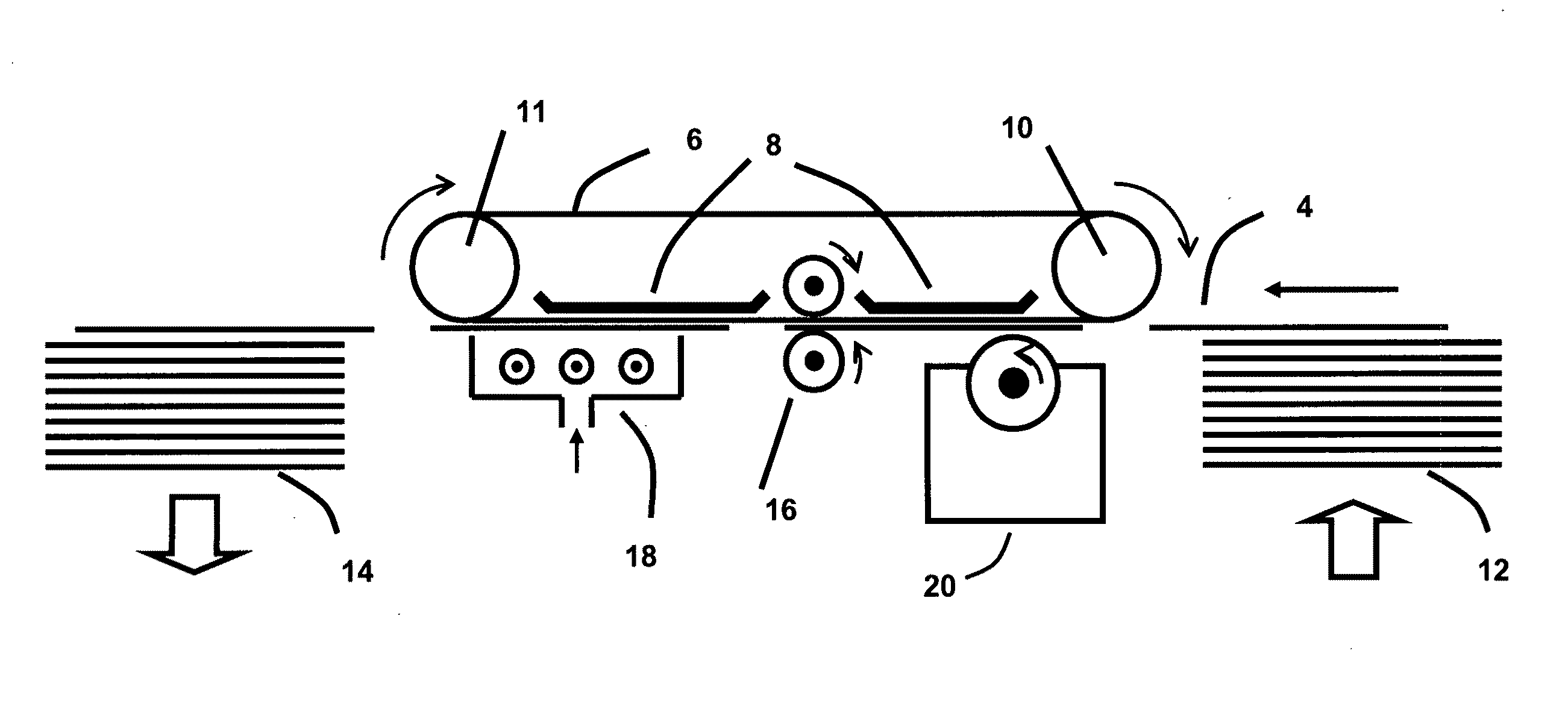
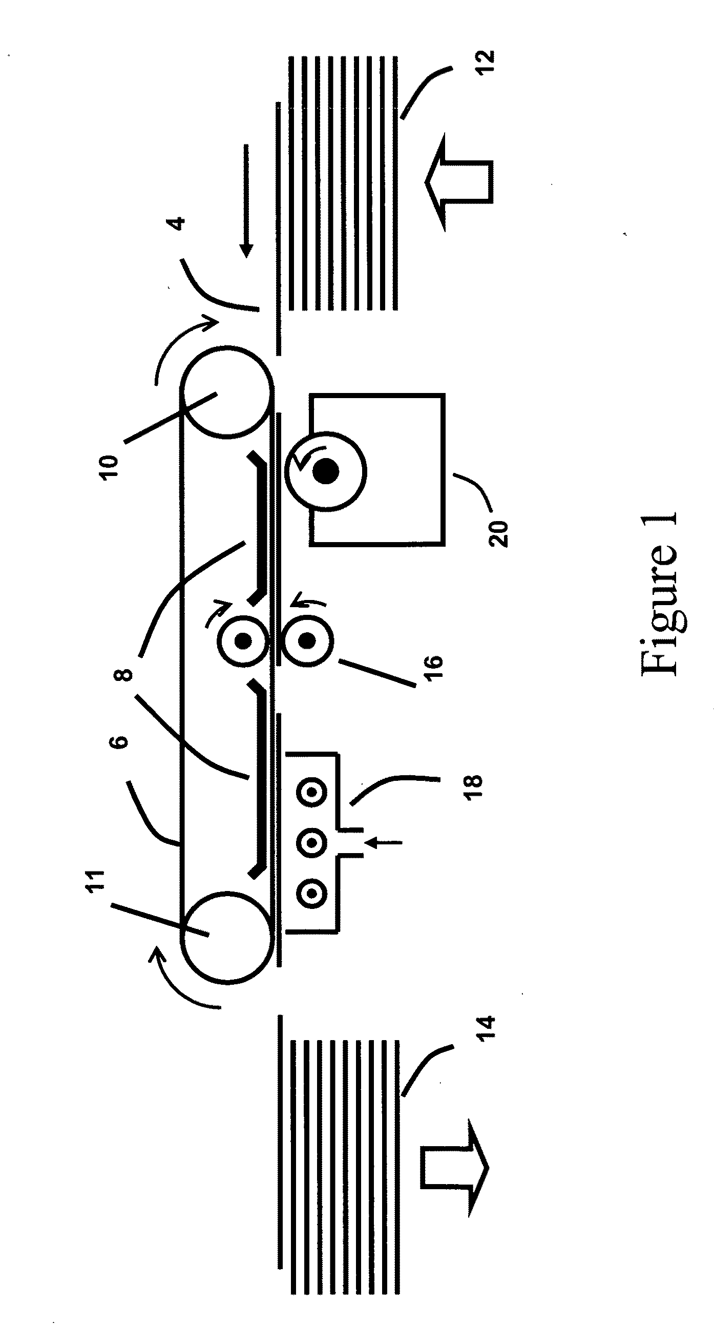
[0050]Hereinafter, a method and apparatus for electrostatic coating insulative or conductive substrates with conductive powder or blends according to this invention will be described with reference to FIGS. 1 through 7. With reference to FIG. 1, an exemplary apparatus and process steps will first be described for coating conductive powder or blends onto supporting substrates. A stack of substrates 12 to be coated of desired size is advanced upward as a single substrate sheet 4 is periodically urged to a substrate-transporting belt 6 for the conveyance of the substrate through different processs stations. The technologies for feeding sheets of materials to be processed by a system are a well-known art in the printing industry. A variety of different mechanisms used in the industry for providing the sheet feeding functionality are applicable to the present invention. The gripping of the substrate to the transporting belt can be obtained by any combination of mechanical, vacuum and ele...

second embodiment

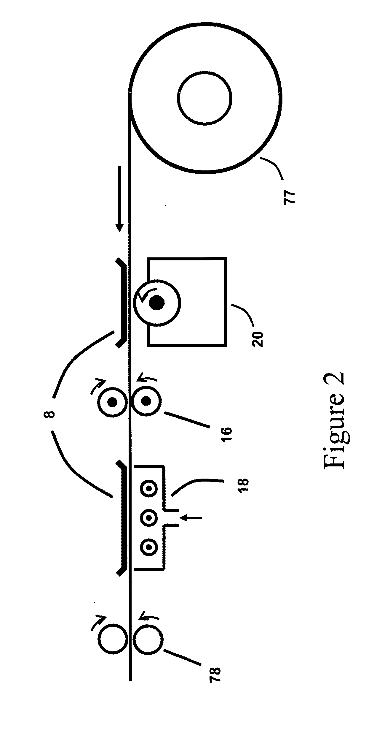
[0076] a variety of methods and apparatus can be used for mixing and transporting the mixture 40 or 41 to the sleeve 26. Such methods are well known from designs for electrophotographic development systems that employ components such as augers, magnetic rollers, buckets, etc. Such methods and apparatus can be incorporated in the apparatus 20 for electrostatic deposition of conductive powder / blend onto a substrate.

third embodiment

[0077] the sleeve 26 can be rotated in either direction to either augment or decrease the mixture 40 or 41 flow rate due to the rotating magnet assembly 28.


PUM


Abstract

A method for manufacturing electrodes using an electrostatic deposition unit. In the first step of the process a mixture of magnetic carrier beads and a conductive powder is prepared in the sump of the deposition unit; the mixture forms a magnetic brush on the sleeve of the deposition unit. In the second step of the process, the substrate is positioned away from the magnetic brush to form an air gap. In the third step of the process, a voltage is applied between the substrate and the sleeve of the deposition unit in order to produce a large asymmetry between the magnetic brush and said substrate such that the electric field at the magnetic brush is at least 3.0 times as great as the electric field at the substrate. In the fourth step of the process, conductive powder is deposited onto the substrate.

Description

FIELD OF THE INVENTION [0001]A method and apparatus for non-interactive electrostatic deposition of an induction charged conductive powder or blend of conductive and insulative powders onto either a conductive or insulative substrate.BACKGROUND OF THE INVENTION[0002]Electrostatic powder spraying is widely used to coat (paint) many consumer products such as appliances, tools, automobiles, etc. Much of the electrophotographic industry for producing high-quality copies and prints is based on the electrostatic deposition of charged powder. Electrostatic powder deposition is also used in a number of manufacturing processes such as abrasive coatings. Most of the applications use a non-magnetic insulative powder that is charged by either triboelectricity or gaseous ions. There are many methods and apparatus for electrostatic charging and depositing non-magnetic insulative powder on either insulative or conductive substrates. The present methods and apparatus for electrostatic powder deposi...

Claims


Application Information

Patent Timeline
IPC IPC(8): B05D1/06
CPCH01M4/04Y02E60/50H01M4/88H01M4/139Y02E60/10
Inventor HAYS, DAN A.MASON, PETER J.MASON, JAMES
Owner XACTIV
Why Eureka
Try Eureka