Tactile objects for orthodontics, systems and methods

a technology of orthodontics and objects, applied in the field of orthodontic appliances, can solve problems such as errors, attachments made by practitioners may not be compatible, and appliance/attachment engagement errors

Active Publication Date: 2011-06-09
ALIGN TECH
View PDF105 Cites 90 Cited by
  • Summary
  • Abstract
  • Description
  • Claims
  • Application Information

AI Technical Summary

Problems solved by technology

Errors may occur as attachments made by the practitioner may not always conform to a prescribed or ideally desired shape and / or may not bond in the correct location or orientation.
Manufacturing limits or errors in attachment or appliance formation (e.g., attachment receiving well of an appliance) may lead to error in appliance / attachment engagement, such as misalignment or less than ideal coupling between an attachment and appliance.
Additionally, wear on an attachment and / or appliance, shape degradation of an appliance, and the like during orthodontic treatment and / or repeated insertion and removal of an appliance may occur, which can further effect force application to the patient's teeth.
Accordingly, a corresponding orthodontic appliance may not ideally couple with the attachment as intended, leading to errors in force delivery and the patient's orthodontic treatment.

Method used


Image

  • Tactile objects for orthodontics, systems and methods
  • Tactile objects for orthodontics, systems and methods
  • Tactile objects for orthodontics, systems and methods

Examples


first embodiment

[0089]FIG. 7A illustrates a method 100 for fabricating an appliance 10 according to a In step 102, a representation of a patient's teeth in a selected arrangement is received. The selected arrangement in particular, and the representation in general, will depend upon the purpose of the particular appliance 10 being defined. Where the appliance 10 will be used to apply positioning forces to constrain a patient's teeth in their current arrangement, the selected arrangement can correspond to the current arrangement of the patient's teeth. Where the appliance 10 will be used to apply repositioning forces to move the patient's teeth from their current arrangement toward a subsequent arrangement, the selected arrangement will typically deviate from the current arrangement of the patient's teeth.

[0090]In step 104, selected teeth of the received representation are optionally modified. This optional modification can include any number of the teeth, from one to all. A wide range of modificat...

second embodiment

[0094]FIG. 7B shows a method 150 for fabricating an appliance 10 according to a In step 152, a digital definition of an appliance is received. The digital definition as received may include adjustments as described above in steps 106 and 108 with respect to FIG. 7A. Additionally or alternatively, the digital definition may be adjusted as described above in steps 106 and 108 after being received.

[0095]In step 154, an appliance 10 is directly fabricated using the digital definition from step 152. Various known manufacturing processes can be used to directly fabricate an appliance 10. In one approach, the appliance 10 is formed by a stereo-lithography fabrication machine, where resin is selectively hardened in the shape of the digital definition.

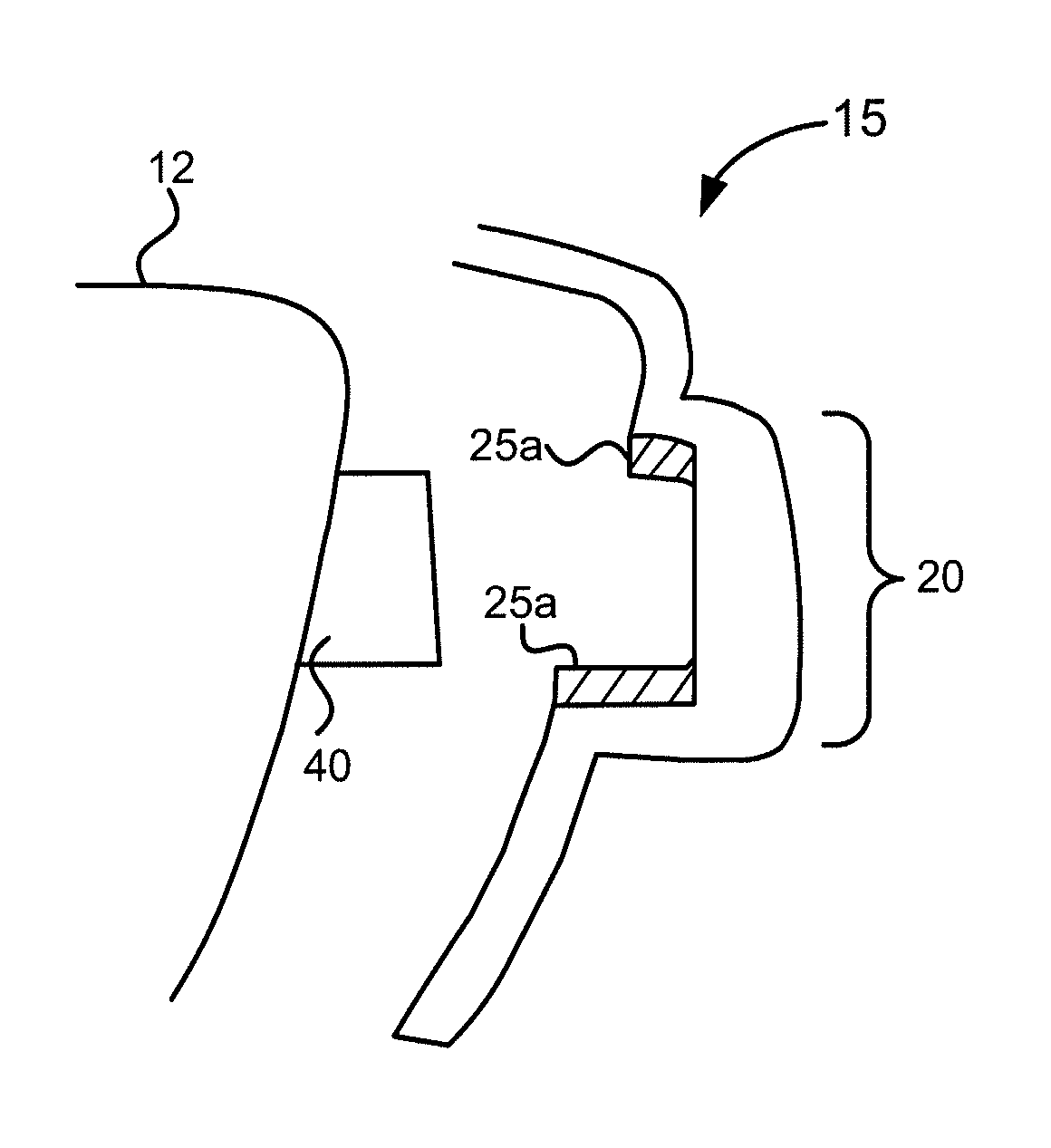
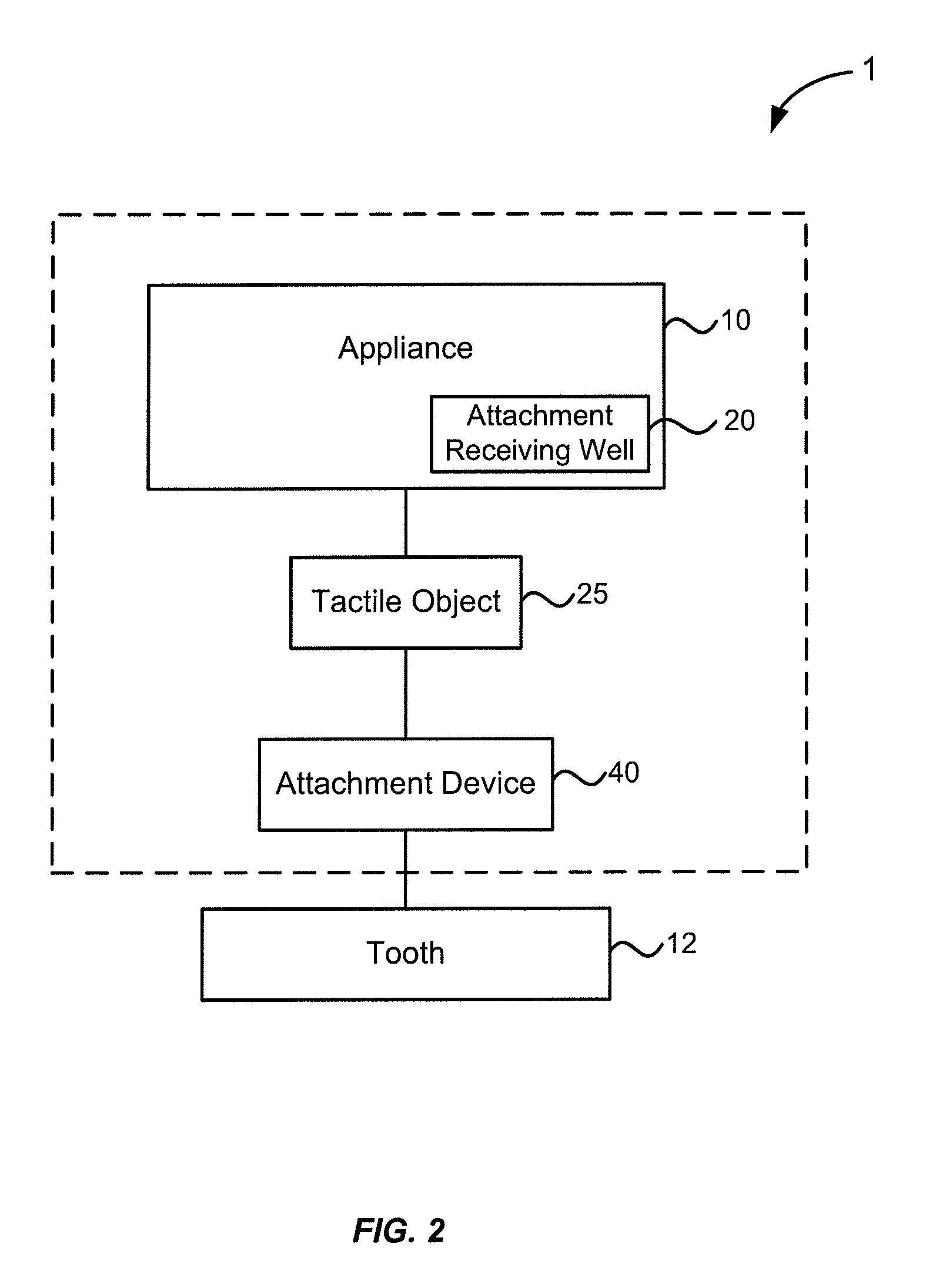
[0096]FIG. 8A shows a method for fabricating a dental template to position an attachment 40 and a tactile object 25 on a patient's tooth 12. In step 210, a patient's tooth 12 is digitized. Next, in step 212, a virtual representation of the att...


PUM

PropertyMeasurementUnit
resilient positioning forceaaaaaaaaaa
elasticityaaaaaaaaaa
forceaaaaaaaaaa

Abstract

Methods, systems, and apparatus's for improving orthodontic treatments. In an embodiment, an orthodontic system including a tactile object is provided for modulating an engagement between a tooth attachment and an orthodontic appliance.

Description

BACKGROUND OF THE INVENTION[0001]The present invention relates generally to the field of orthodontics, and more particularly to orthodontic appliances, such as shell appliances, and tactile objects for improving the affects of attachment devices.[0002]An objective of orthodontics is to move a patient's teeth to positions where function and / or aesthetics are optimized. Traditionally, appliances such as braces are applied to the patient's teeth by an orthodontist or dentist and the set of braces exerts continual force on the teeth and gradually urges them toward their intended positions. Over time and with a series of clinical visits, the orthodontist adjusts the appliances to move the teeth toward their final destination.[0003]More recently, alternatives to conventional orthodontic treatment with traditional affixed appliances (e.g., braces) have become available. For example, systems including a series of preformed orthodontic appliances have become commercially available from Align...

Claims


Application Information

Patent Timeline
Patent Type & Authority Applications(United States)
IPC IPC(8): A61C7/00B23P13/00
CPCA61C7/08Y10T29/49568B33Y80/00A61C7/14
Inventor LI, CHUNHUACHEN, JENNIFERMORTON, JOHNMOSS, JONKAUFHARDT, CLARKCAO, HENG
Owner ALIGN TECH
Why Eureka
Try Eureka