Orthodontic device

a technology for orthodontic devices and orthodontic implants, which is applied in the field of orthodontic/orthognathic devices, can solve the problems of lack of individualization, lack of control, and conventional distalization appliances, and achieve the effects of excellent treatment options, constant tension, and elimination of crowding

Active Publication Date: 2016-05-10
ALYAMI BANDAR
View PDF29 Cites 8 Cited by
  • Summary
  • Abstract
  • Description
  • Claims
  • Application Information

AI Technical Summary

Benefits of technology

[0011]The orthodontic / orthognathic device is capable of exerting force on a tooth or bone structure in a predictable and stepwise fashion. By controlling the electric motor of the orthodontic device with a microcontroller that is included in the housing in which the electric motor is located permits customization of treatment plan and the application of force in a constant manner thus avoiding the necessity of several repeated visits to an orthodontic practitioner.
[0012]In one aspect of the invention the orthodontic device is attached to the palate, for example, with one or more mini screws. An electromotor powered by a battery (rechargeable) housed together or separately from the orthodontic device provides constant tension to a tooth through one or more lever arms that are connected to both the electromotor and a tooth. The electromotor may be programmed to provide tension to one or more teeth such that the teeth can be moved mesially, distally, buccally, labially, lingually, up or down direction with respect to the original tooth location. Any tooth may be connected to the electromotor and may be subject to tension or force through one or more lever arms. Orthodontic device can be an excellent treatment option for patient that has crowding and needs spaces to eliminate crowding with better and predictable result.
[0014]In a still further aspect of the invention computerized maxillary distraction is accomplished with the orthodontic and / or orthognathic device of the invention. Using electromotors positioned in a motor housing and programmed with instructions to move bones in particular direction in three dimensions permits facial changes and rearrangements both with functional, cosmetic and medical purposes. Computer control permits gentle and continuous exertion of force to improve patient comfort levels and reduce daily adjustment management. Maxillary movement can be programmed in three dimensions to accomplish advancement of maxilla but also to correct asymmetry or cant of the maxilla and / or change the morphology of bone and the growth patterns in cranial facial structures of a patient. Constricted and deficient maxilla can be expanded and advanced with a single orthognathic and / or orthodontic device. Conventionally such movement required two different devices and / or corrective appliances.

Problems solved by technology

This uncontrolled system shows the lack of individualization to fit specific needs of each patient and solve each problem independently.
A distalization appliance can be an excellent option to move the posterior teeth distally and create enough space especially with deep bite cases, but conventional distalization appliances suffer from difficulty and the lack of control which makes this kind of appliance incompletely effective.
Distraction osteogenetic devices are encumbered with difficulties relating to controlling the direction of movement and force applied to a bone and with cooperation of the patient who may be under distress or discomfort caused by the device.
Such modifications usually require the intervention of an orthodontic, surgeon or other medical care professional at relatively great inconvenience and discomfort to the patient.
Like orthodontic expanders, distraction osteogeneis devices often require daily maintenance and adjustment, e.g., by turning screws.
These variances arise for many reasons; one of the main reasons is the lack of a device and / or method that can produce accurate and reproducible force and tooth movement.
The inconsistencies and low reproducibility of conventional devices can lead to inaccuracies during the experiments and difficulties in reproducing results.

Method used


Image

  • Orthodontic device
  • Orthodontic device
  • Orthodontic device

Examples


Embodiment Construction

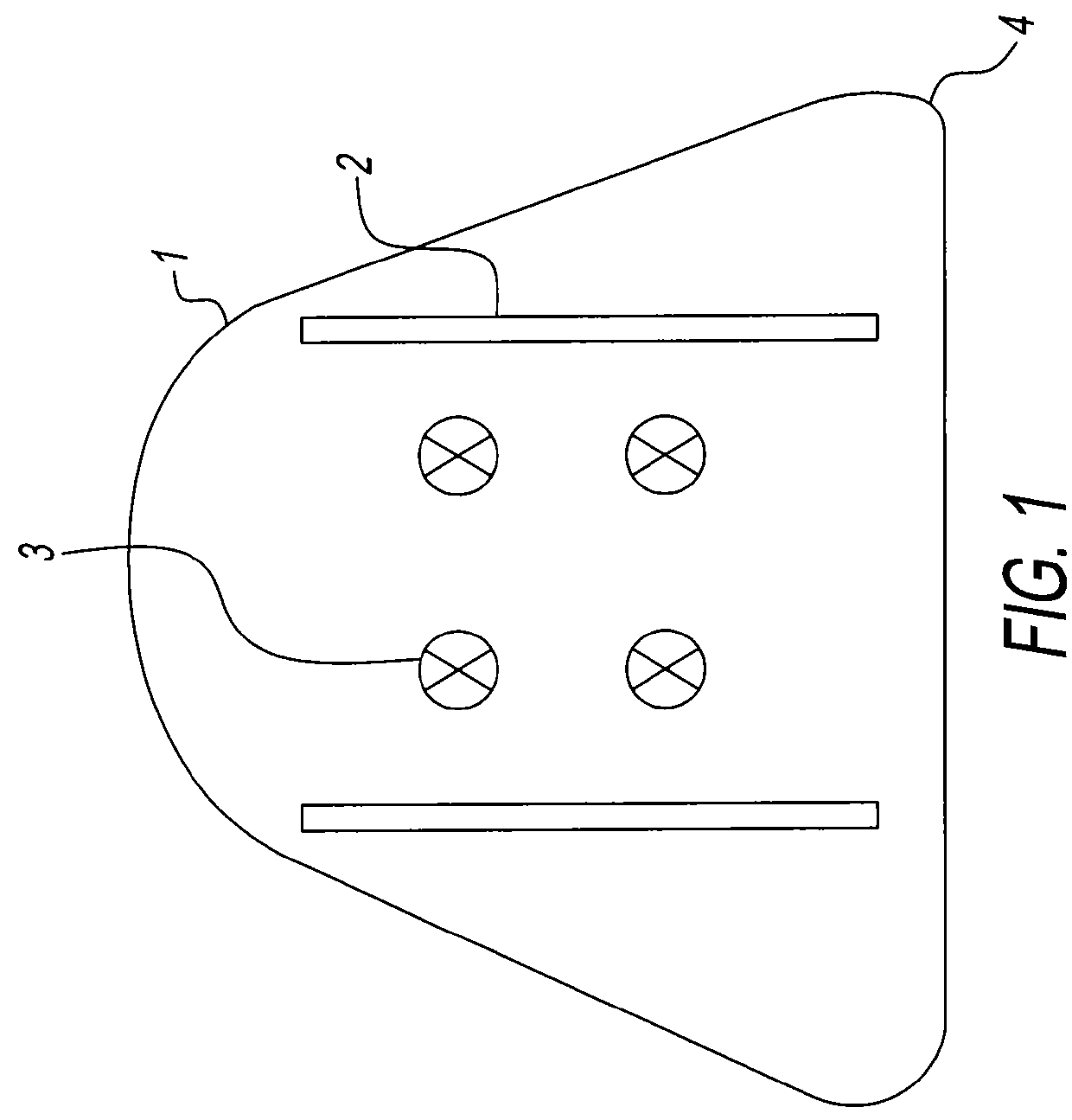
[0034]Conventional orthodontic devices or appliances are universal appliances that are applied to all patients with lack of individualization to fit specific need of each patient and solve each problem independently. Even such relatively simple movement is disadvantaged because it requires anchoring the orthodontic device, e.g., edgewise system, to other teeth. Thus the movement of a single tooth with a conventional orthodontic device may often result in movement of other teeth. This problem can be especially serious for patients having one or more teeth, which are unsuitable for anchorage and / or unsuitable for movement or contact with an orthodontic device.

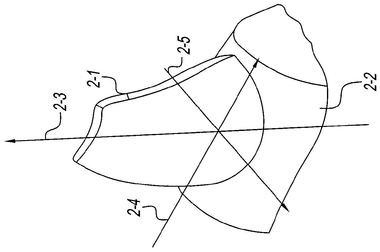
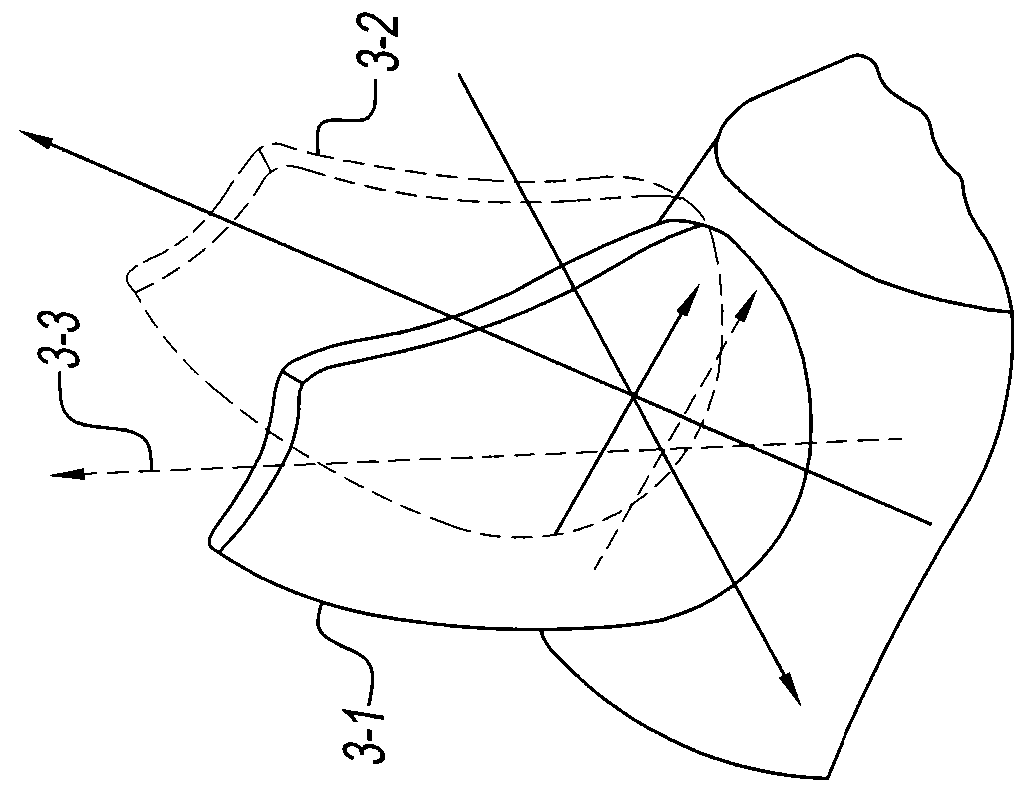
[0035]Utilizing a motor mounted to the palate or other bone permits movement of single teeth in three dimensions. A tooth may be rotated, extruded / intruded, or labial / buccally, mesial / distally moved. A single tooth can be moved independently of other teeth or may be moved in conjunction with one or more teeth which are subject to...


PUM

PropertyMeasurementUnit
pulling forcesaaaaaaaaaa
speedsaaaaaaaaaa
forcesaaaaaaaaaa

Abstract

An orthodontic / orthognathic device for correcting and changing tooth placements and bone structure, and a method of using orthodontic / orthognathic device for tooth movement, correcting syndromic conditions of the mouth and osteogenetic correction. The device may be used for maxillary distraction and expansion as well as mandibular separation and expansion. The device can be controlled by computer to direct tooth and bone placement.

Description

GRANT OF NON-EXCLUSIVE RIGHT[0001]This application was prepared with financial support from the Saudi Arabian Cultural Mission, and in consideration therefore the present inventor(s) has granted The Kingdom of Saudi Arabia a non-exclusive right to practice the present invention.FIELD OF THE INVENTION[0002]The present invention relates to orthodontic / orthognathic device for correcting and changing tooth placements and bone structure, and a method of using orthodontic / orthognathic device for tooth movement, correcting syndromic conditions that affect the face and jaws. The device can be controlled by computer to direct tooth and bone placement.BACKGROUND OF THE INVENTION[0003]In 1928 conventional edgewise-orthodontic appliance was introduced by Edward H. Angle, and is considered as the foundation for the numerous appliance systems commercially available today. Different adjustments have been added to the system such as direct bonded bracket, twin brackets, different dimensions, lingua...

Claims


Application Information

Patent Timeline
Patent Type & Authority Patents(United States)
IPC IPC(8): A61C3/00A61C7/10A61B17/66A61C7/06A61C7/00A61B17/00
CPCA61C7/10A61B17/663A61C7/002A61C7/06A61B2017/00221A61B17/3472A61B17/8071A61B34/35A61C7/145A61C8/0096A61K9/06A61K35/32A61K45/06A61K47/36
Inventor ALYAMI, BANDAR
Owner ALYAMI BANDAR
Why Eureka
Try Eureka