
Miniature flow-through cuvette and spectrophotometer containing the same

a flow-through cuvette and spectrophotometer technology, applied in the field of miniature flow-through cuvettes and spectrophotometers, can solve the problems of increasing the ratio of surface area to volume of sample mixture, and affecting the accuracy of measurement results

Inactive Publication Date: 2011-06-16
BOULA MEDICAL AB
View PDF11 Cites 14 Cited by
  • Summary
  • Abstract
  • Description
  • Claims
  • Application Information

AI Technical Summary

Problems solved by technology

A known problem in the existing measurement is attachment of micro-bubbles in the sample mixture to the walls of the cuvette, which causes errors in the measurement.
However, when the dimensions of the flow path in the cuvette decrease, the ratio of surface area to the volume of the sample mixture increases, and prevention of micro-bubble attachment becomes substantially more difficult.
Although these hematology analyzers have known advantages of high capacity, batch sample analysis, automated sample aspiration and preparation, and automated cleaning cycles, these instruments are relatively high cost and use large quantity of reagents, which requires high maintenance of the instruments and reagent inventory management.
Therefore, it is difficult to adapt these instruments in a near-patient test environment, such as in the emergency room, where a minimum sample volume and minimum reagent maintenance are required.
This significantly increases the ratio of surface area of the flow path to the volume of the sample mixture, and renders extremely difficult to control micro-bubble formation and attachment within the cuvette when the sample mixture passes through and when it is measured in the cuvette.
Moreover, it is also technically challenging to remove micro-bubbles attached to or accumulated in the cuvette using a small volume of a cleaning solution provided in the cassette only.

Method used


Image

  • Miniature flow-through cuvette and spectrophotometer containing the same
  • Miniature flow-through cuvette and spectrophotometer containing the same
  • Miniature flow-through cuvette and spectrophotometer containing the same

Examples


Embodiment Construction

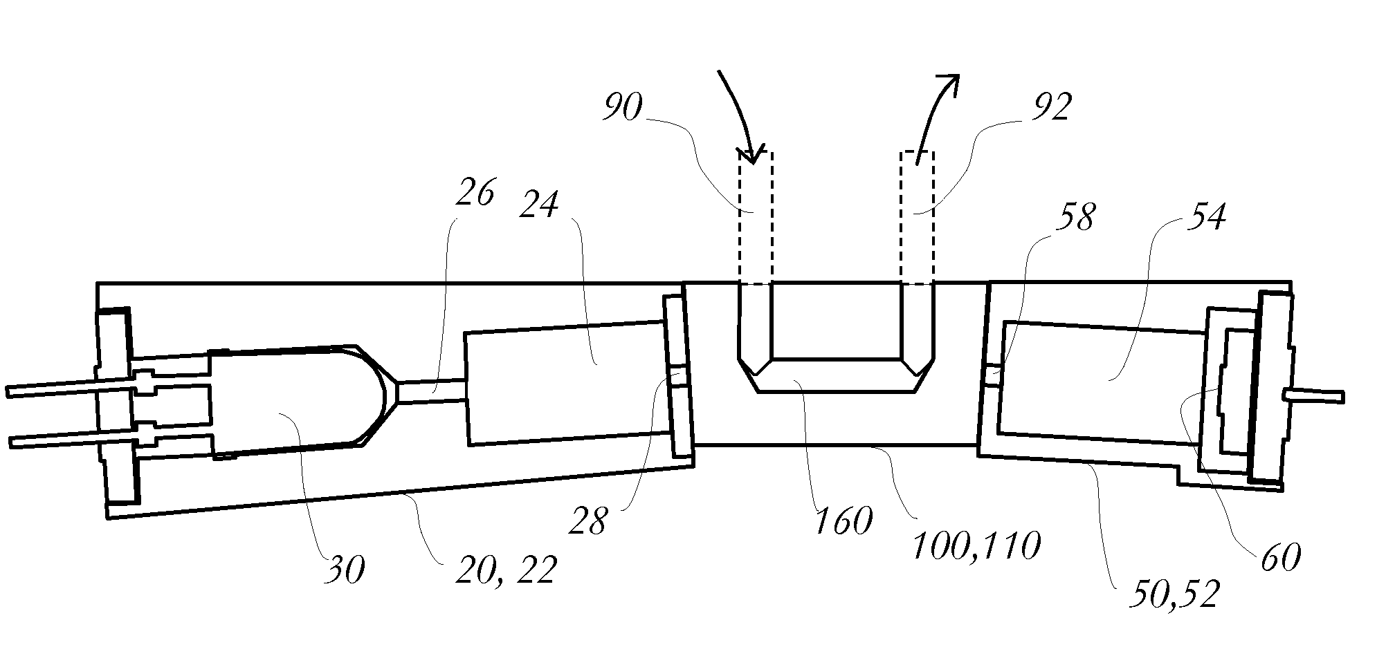
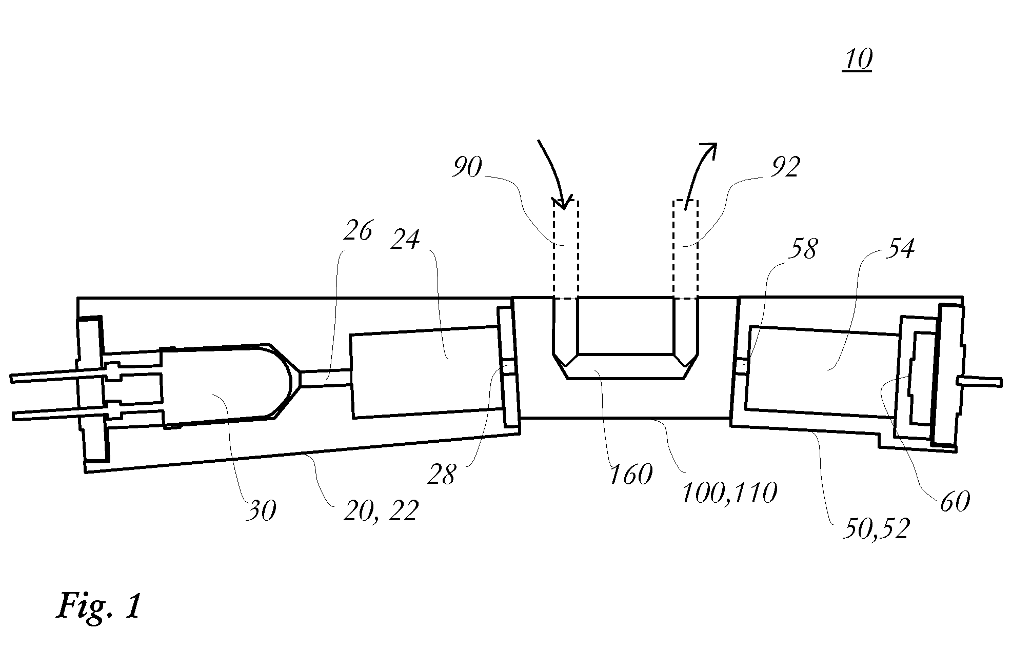
[0023]In one aspect, the present invention provides a spectrophotometer that comprises a miniature flow-through cuvette for measurement of a liquid sample flowing therethrough. As shown in FIG. 1, in one embodiment spectrophotometer 10 includes a miniature flow-through cuvette 100, a light source 20, and a photo detector 50.

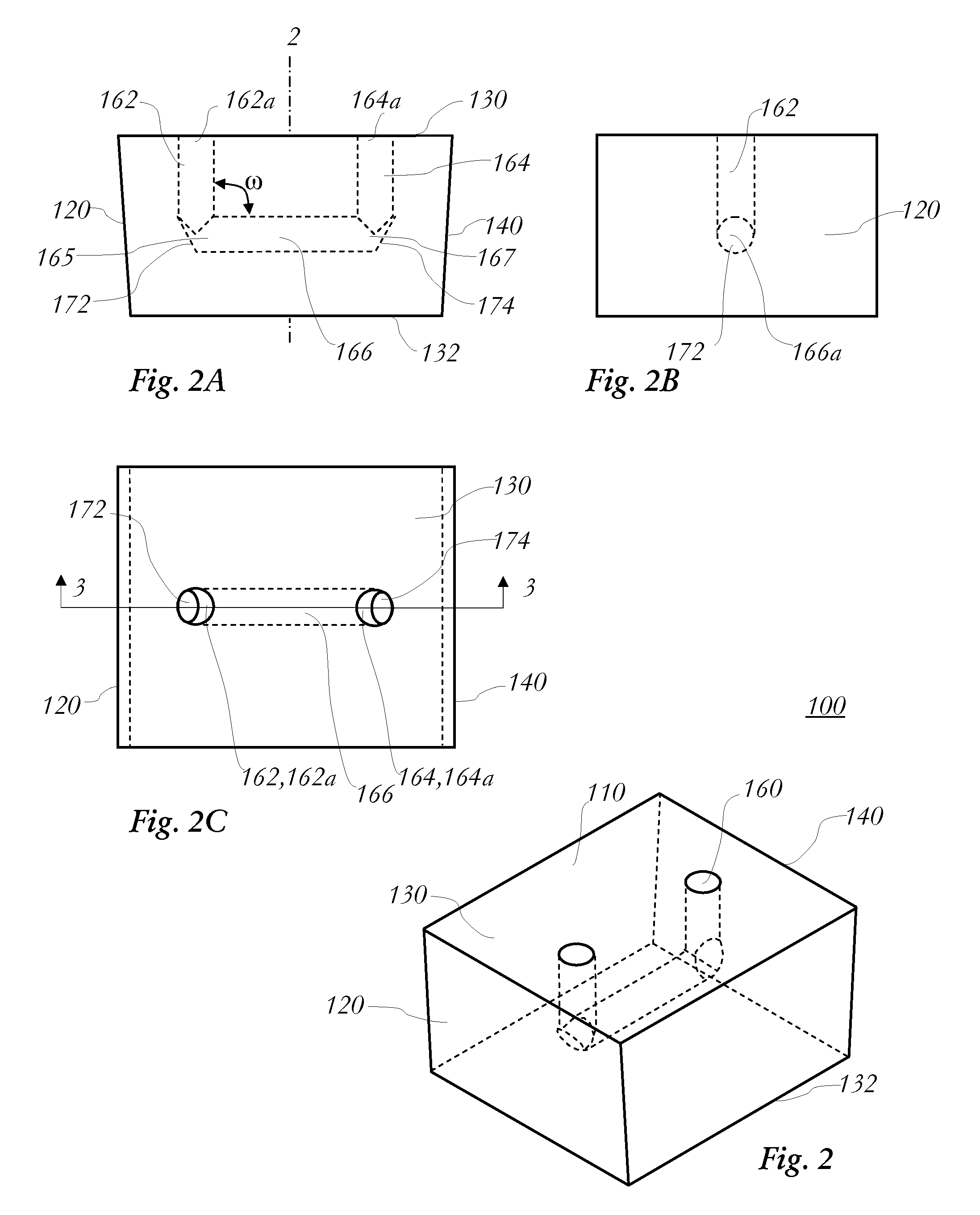
[0024]FIGS. 2 to 3A show a miniature flow-through cuvette 100 in one embodiment of the present invention. The flow-through cuvette 100 has a cuvette body 110 made of a transparent material. Cuvette body 110 has an upper side 130, a bottom side 132, a first outer surface 120, and an opposing second outer surface 140. Both the first and second outer surfaces, or at least the areas of the first and second outer surfaces in line with the measurement segment of the flow channel as described hereinafter, are planar. In the exemplary embodiment shown, both first and second outer surfaces 120 and 140 are inclined relative to the vertical axis 2 of cuvette body 110. Howev...


PUM


Abstract

A miniature flow-through cuvette for spectrophotometric measurement of a liquid sample includes a cuvette body of a transparent material including a first outer surface and an opposing second outer surface, and a flow channel disposed through the cuvette body. The flow channel includes first and second interface segments generally vertically oriented, each having an open exit; a measurement segment interconnecting the first and second interface segments; a first inclined planar inner surface disposed in a turning segment between the first interface segment and the measurement segment, facing the first outer surface; and a second inclined planar inner surface disposed in a turning segment between the second interface segment and the measurement segment, facing the second outer surface. The first and second inclined inner surfaces terminate the measurement segment at opposing ends thereof. Further provided is a spectrophotometer including the miniature flow-through cuvette.

Description

FIELD OF THE INVENTION[0001]The present invention relates to a miniature flow-through cuvette and a spectrophotometer including such a miniature flow-through cuvette for measurement of a liquid sample, and particularly for spectrophotometric measurement of a blood sample on a blood analyzer.BACKGROUND OF THE INVENTION[0002]Spectrophotometric measurement of hemoglobin concentration of a blood sample has been used for decades on hematology analyzers. Typically, a blood sample is exposed to a lytic reagent to lyse the red blood cells, and then the released hemoglobin molecules in the sample mixture form a chromogen with a ligand or stabilizer in the reagent. A flow of the sample mixture is delivered through a cuvette in the analyzer, and absorption of the sample mixture is measured and used to calculate hemoglobin concentration of the blood sample.[0003]In the existing hematology analyzers, commonly the measurement window of the cuvette includes two opposing parallel walls disposed alo...

Claims


Application Information

Patent Timeline
IPC IPC(8): G01J3/42B01L3/00
CPCB01L3/502715B01L2200/0689B01L2300/0654G01N2021/054G01N21/05G01N2021/0346G01N2021/0396B01L2300/0877
Inventor MAGNUSSON, GUNNARROOS, BJORN
Owner BOULA MEDICAL AB
Learn More