Connection assembly

a technology of connecting parts and assembly, which is applied in the direction of coupling device connections, coupling parts engagement/disengagement, two-part coupling devices, etc., can solve the problems of loosening and affecting the connection, and achieve the effect of increasing reducing the inside diameter of the spring

Inactive Publication Date: 2011-06-16
RADIALL SA
View PDF8 Cites 12 Cited by
  • Summary
  • Abstract
  • Description
  • Claims
  • Application Information

AI Technical Summary

Benefits of technology

Exemplary embodiments of the invention provide a device for connecting together first and second complementary connector elements, in particular a plug and a socket, the device comprising first and second parts that are movable in rotation relative to each other, wherein the device comprises a spring having a first end connected to the first part and a second end connected to the second part; the spring, the first part, and the second part being such that turning the first part in a first direction of rotation, or turning the second part in a second direction of rotation opposite to the first direction of rotation increases the inside diameter of the spring; and the spring, the first part, and the second part being such that turning the first part in the second direction of rotation or turning the second part in the first direction of rotation decreases the inside diameter of the spring.

Problems solved by technology

Such solutions do not serve to avoid unwanted loosening of the ring, where such loosening affects the connection that is made and occurs in particular under the effect of vibration or of rotation of the cable on which the plug is mounted.

Method used


Image

  • Connection assembly
  • Connection assembly
  • Connection assembly

Examples


first embodiment

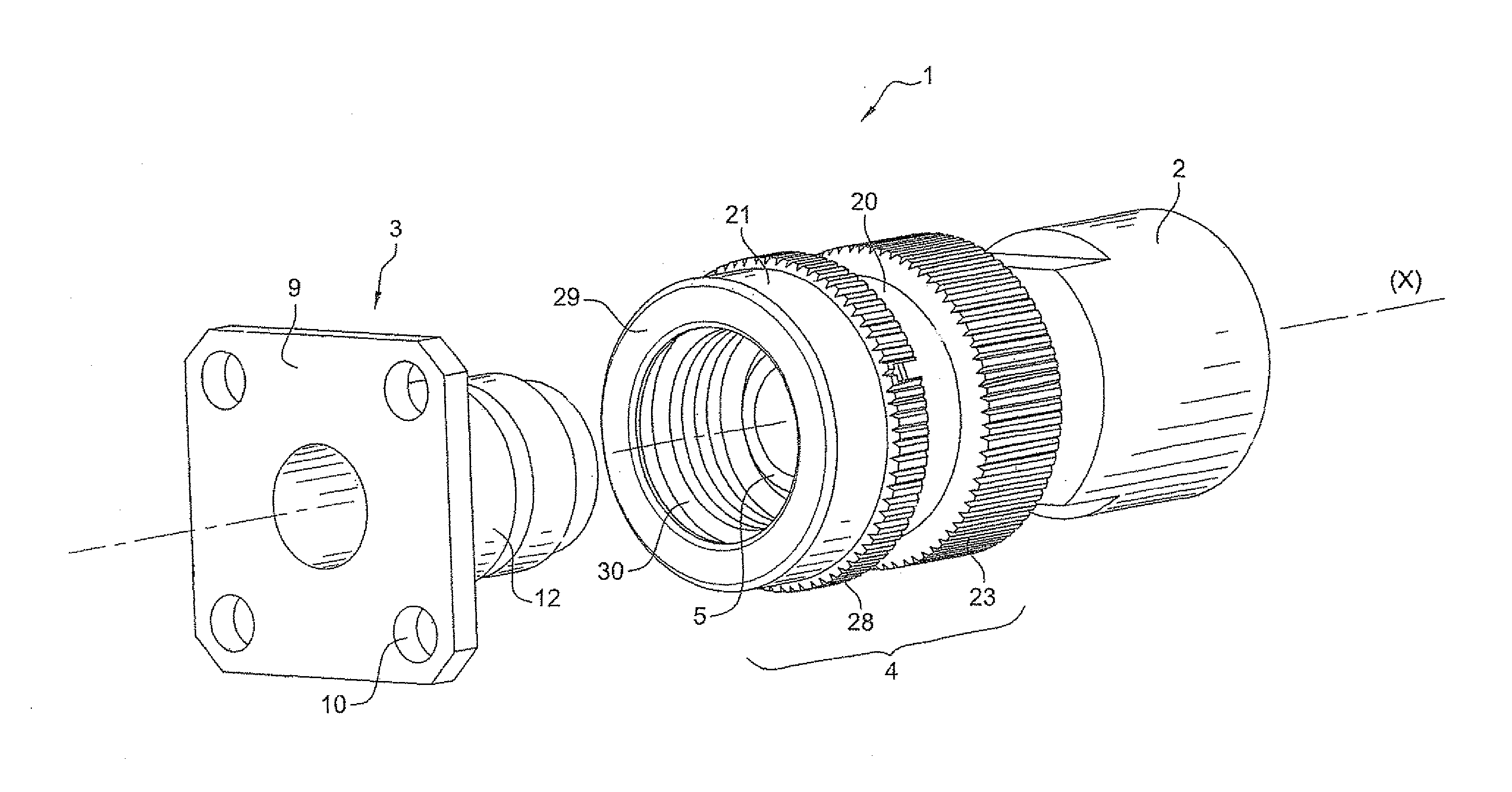
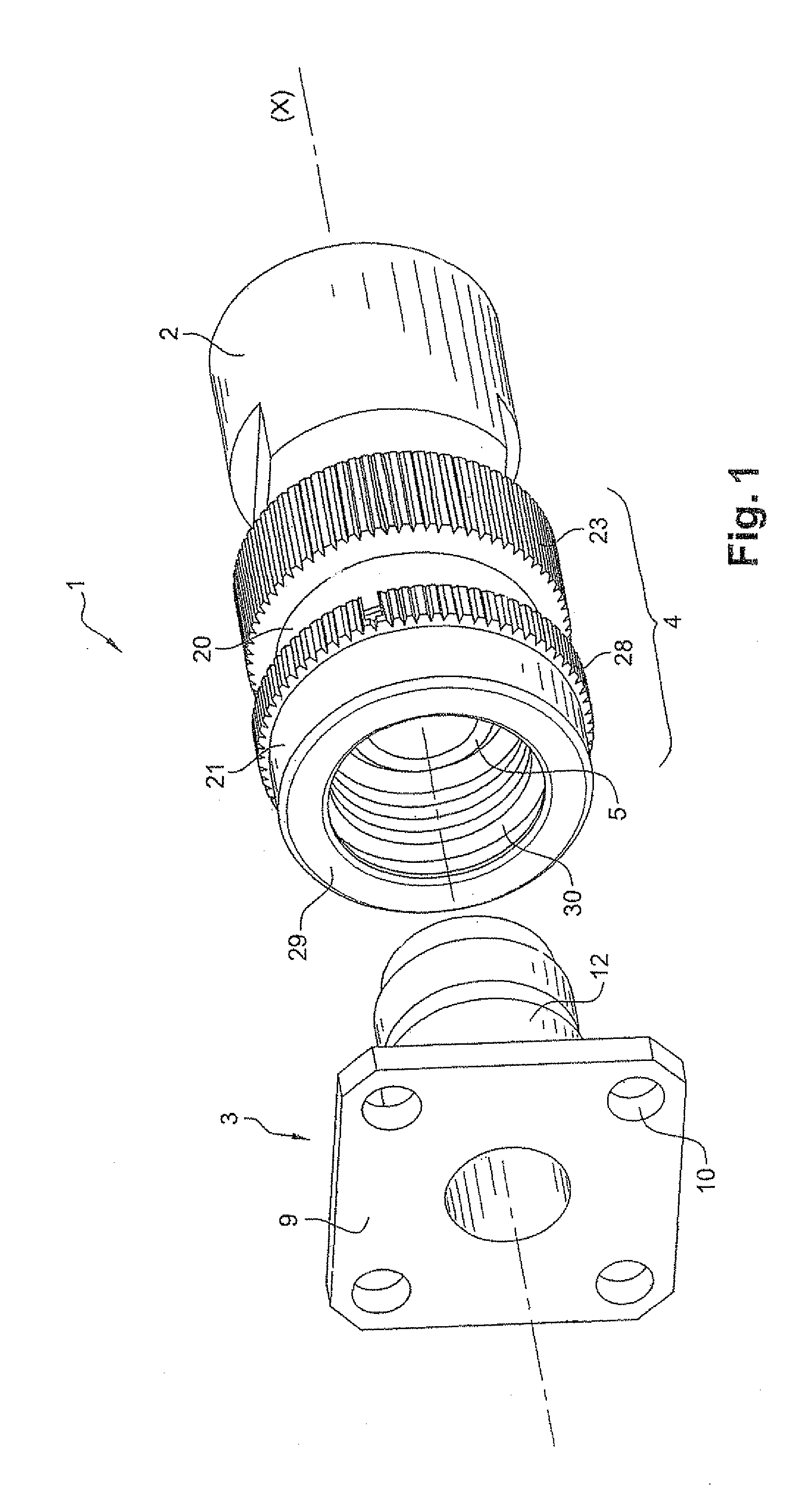
FIG. 1 shows an assembly given overall reference 1 in the invention.

This assembly 1 comprises a first connector element 2 suitable for being connected to a complementary, second connector element, given overall reference 3, by means of a device that is given overall reference 4. In the example described, but in non-limiting manner, the first connector element 2 is a plug and the second connector element 3 is a socket. In a variant, the second connector element 3 is an outlet for wiring.

In the example described, the plug 2 and the socket 3 are coaxial elements of internal structure that comprises a central contact received in an outer contact with insulation interposed between them (not shown in FIGS. 1 to 4 for reasons of clarity).

By way of example, the plug 2 is generally tubular in shape about a longitudinal axis X, presenting a cross-section that decreases in steps on approaching the front end 5 of the plug 2, said end 5 designating the longitudinal end of the plug 2 that comes i...


PUM


Abstract

The present invention provides a device for connecting together first and second complementary connector elements, the device comprising first and second parts that are movable in rotation relative to each other, wherein the device comprises a spring having a first end connected to the first part and a second end connected to the second part; the spring, the first part, and the second part being such that turning the first part in a first direction of rotation, or turning the second part in a second direction of rotation opposite to the first direction of rotation increases the inside diameter of the spring; and the spring, the first part, and the second part being such that turning the first part in the second direction of rotation or turning the second part in the first direction of rotation decreases the inside diameter of the spring.

Description

FIELD OF THE INVENTIONThe present invention relates to a device for connecting together two complementary connector elements, e.g. a plug to a socket or to an outlet for wiring. By way of example, the connector elements may be coaxial elements, in particular a coaxial plug and a coaxial socket.BACKGROUND OF THE INVENTIONIt is known to make such a connection by means of a ring that is mounted to turn on a plug, the ring including a thread for screwing onto a corresponding thread of the socket. The ring is tightened and loosened by turning it in two opposite directions of rotation.Such solutions do not serve to avoid unwanted loosening of the ring, where such loosening affects the connection that is made and occurs in particular under the effect of vibration or of rotation of the cable on which the plug is mounted.There exists a need to have a device for connecting a plug to a socket that reduces the risk of unwanted loosening.OBJECT AND SUMMARY OF THE INVENTIONExemplary embodiments o...

Claims


Application Information

Patent Timeline
Patent Type & Authority Applications(United States)
IPC IPC(8): H01R13/62
CPCH01R13/622H01R24/40H01R13/6395
Inventor MEYNIER, CHRISTOPHE
Owner RADIALL SA
Why Eureka
Try Eureka