
Material removal device having improved material capture efficiency and methods of use

a technology of material removal device and material capture, which is applied in the field of catheters, can solve the problems of low blood flow, skin ulceration, scar formation in a high percentage of patients, and pain in the legs,

Inactive Publication Date: 2011-06-16
FOX HOLLOW TECH
View PDF99 Cites 153 Cited by
  • Summary
  • Abstract
  • Description
  • Claims
  • Application Information

AI Technical Summary

Problems solved by technology

Over time atheromatous deposits can become large enough to reduce or occlude blood flow through the vessels, leading to symptoms of low blood flow such as pain in the legs (on walking or at rest), skin ulcer, angina (at rest or exertional), and other symptoms.
The atheroma deposits can be displaced by diametrically expanding the vessel by inflating balloons, expanding stents, and other methods, however these methods undesirably tear and stretch the vessel, causing scar formation in a high percentage of patients.
The deposits can be pulverized using lasers and other methods however pulverization alone of atheromatous material allows microemboli to flow downstream and lodge in distal vascular beds, further compromising blood flow to the tissue affected by the disease.
One problem that occurs when removing material from a blood vessel is that material fragments may be created by the removal means, in some cases by a cutter, and such fragments may be left in the body where they can embolize and cause problems.
Some catheters are designed to remove material from the body by directing material particles into a collection chamber however these collection efforts are not always 100% effective.

Method used


Image

  • Material removal device having improved material capture efficiency and methods of use
  • Material removal device having improved material capture efficiency and methods of use
  • Material removal device having improved material capture efficiency and methods of use

Examples


Embodiment Construction

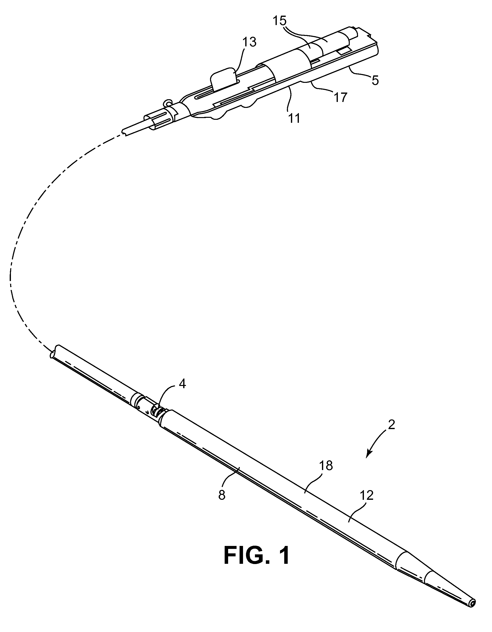
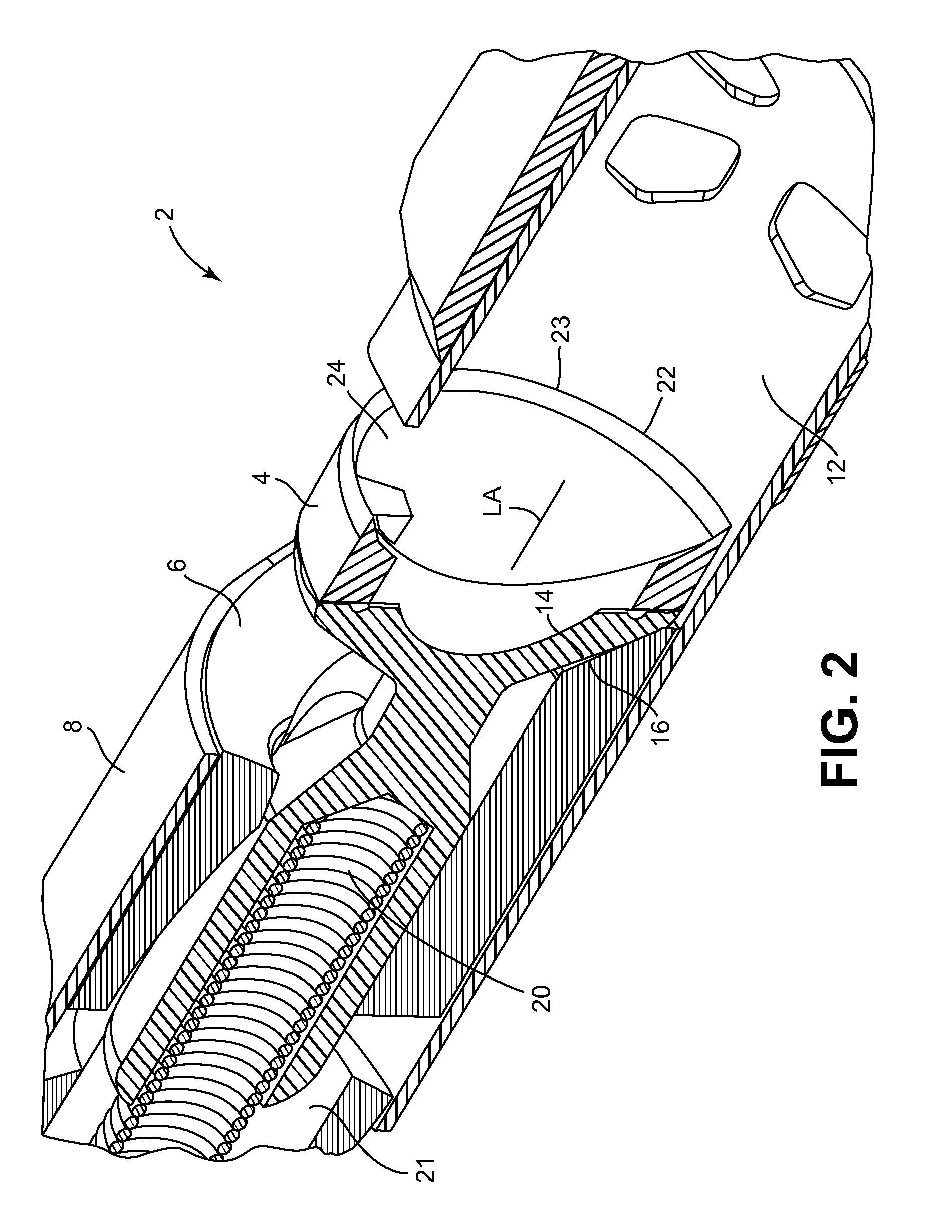
[0023]The invention provides an atherectomy catheter, comprising: a body having an opening; a rotatable shaft coupled to the body; a tissue collection chamber coupled to the body and positioned distal to the cutting element; a cutting element coupled to the rotatable shaft, the cutting element having a cutting edge; and a lumen configured to direct fluid into the tissue collection chamber. In one embodiment, the lumen directs fluid in a distal direction into the tissue collection chamber. In one embodiment, the cutting element has a cup-shaped surface, the cup-shaped surface being configured to re-direct tissue cut by the cutting edge in a distal direction when the cup-shaped surface moves in the distal direction. In one embodiment, the lumen has a distal opening on the cup-shaped surface of the cutting element. In an embodiment, the lumen comprises a first lumen portion in the cutting element and a second lumen portion in the rotatable shaft. In one embodiment, the distal opening i...


PUM


Abstract

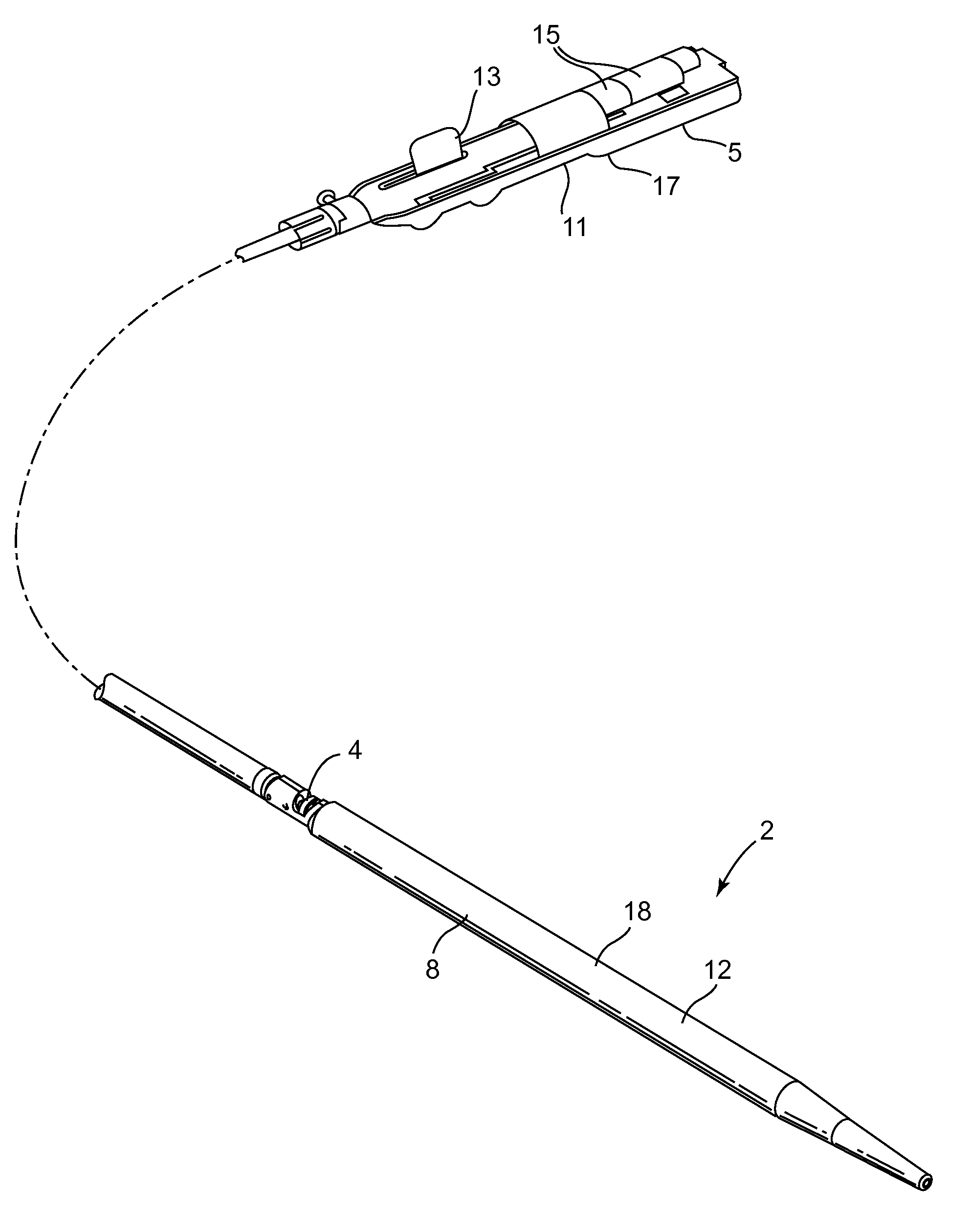
The present invention provides an improved atherectomy catheter having means for directing particles generated by a cutting element into a collection chamber. Methods of directing the cut material from a blood vessel lumen into a collection chamber are also provided.

Description

[0001]This application claims the benefit of U.S. Provisional Patent Application No. 61 / 285,768, filed Dec. 11, 2009, entitled “Material Removal Device Having Improved Material Capture Efficiency and Methods of Use”, the contents of which are hereby incorporated by reference herein.FIELD OF THE INVENTION[0002]The present invention relates to catheters used to remove material from a site in a body lumen. More particularly, this invention pertains to catheters capable of capturing the material removed from the site.BACKGROUND OF THE INVENTION[0003]Atherosclerosis is a progressive disease of the vascular system whereby atheroma is deposited on the inner walls of blood vessels. Over time atheromatous deposits can become large enough to reduce or occlude blood flow through the vessels, leading to symptoms of low blood flow such as pain in the legs (on walking or at rest), skin ulcer, angina (at rest or exertional), and other symptoms. To treat this disease and improve or resolve these sy...

Claims


Application Information

Patent Timeline
IPC IPC(8): A61B17/22
CPCA61B17/320758A61B17/320783A61B2017/320791A61B2017/320032A61B2017/320064A61B2017/00685A61B17/22A61B17/3207
Inventor ZHANG, ZHIYONGMOBERG, JOHN ROBERTRANGWALA, HUSSAIN S.MCPEAK, THOMAS JOHNWHEALON, WILLIAM JOSEPHKUSLEIKA, RICHARD S.
Owner FOX HOLLOW TECH
Learn More