Expandable tip atherectomy method and apparatus

a technology of expanding tip and atherectomy, which is applied in the field of rotating ablator tip, can solve the problems of reducing the desirability and/or effectiveness of coronary bypass surgery, invasive, risky surgery, etc., and achieves the effects of reducing the circumference, facilitating the introduction of the balloon, and reducing the circumferen

Inactive Publication Date: 2000-07-04
ZACCA NADIM M
View PDF53 Cites 115 Cited by
  • Summary
  • Abstract
  • Description
  • Claims
  • Application Information

AI Technical Summary

Benefits of technology

The present invention comprises apparatus and methods for removing obstructions from vessels or small openings in the body. The apparatus is guided into the vessel having the obstruction. The tip of the apparatus comprises a short length of ovaloid shaped coil that can be elongated, thereby decreasing its circumference as compared to its circumference in the normal wound configuration. Lengthening and rotating the coil reduce its circumference and facilitate its introduction to an obstructed area. The coil is then allowed to return to a normal wound configuration thereby increasing the overall circumference of the coil. At least part of the outer surface of the coil is abrasive. The coil can be enlarged to a preselected circumference between the normal wound configuration and the elongated smaller circumference. The coil is rotated at the point of the obstruction to break up the obstruction and clear the vessel. The above ovaloid shaped coil resembles a spiral lemon peel.
The coil diameter can be selectively decreased and increased as desired to reach and treat, respectively, the obstruction in the vessel. The coil's circumference can be increased or decreased over a range by a remotely actuated means that will elongate or retract the coil as desired. This permits the use of introducers and guiding catheters of smaller diameters than is common in the present practice of device introduction, resulting in less trauma to the patient's vessels at the site of introduction and en route to the obstruction, and also simplifying the procedure.
The ability of the tip to adjust to a desired diameter, within the maximum and minimum range, permits the progressive, from smaller to larger, enlargement of a passage through a stenotic obstruction. The variable tip diameter permits the use of a single device of the present invention to more fully clear a stenosis without the need to use two or more of the existing fixed diameter atherectomy devices. The present treatment of stenosis, with fixed diameter atherectomy devices, in addition to requiring the use of two or more cutting devices almost always requires the use of an angioplasty balloon catheter as a final treatment. A single device of the present invention will fully treat a stenosis, thus shortening the procedure, reducing trauma, and reducing procedure cost.
After an obstruction is cleared, it is possible to decrease the circumference of the coil by elongation and easily withdraw the coil and associated catheter from the vessel.
The coil tip is rotated at a desired speed during its passage through the stenosis. Once the obstruction is cleared, the coil is returned to its original smaller diameter and may be easily withdrawn from the vessel.

Problems solved by technology

Traditionally, patients have had to undergo relatively complex, invasive, and risky coronary bypass surgery in order to obviate or reduce the obvious health hazards presented by occluded coronary arteries.
The inflated balloon tends to crush or compact the obstructing material against the vessel walls as well as crack the obstructing material and dilate the vessel so as to increase the lumen or passageway therethrough, but does not remove the obstructing material from the vessel.
Since the cracked and fractured obstructing material is not removed, there is a significant possibility that the vessel will become reoccluded at the treated area within a relatively short period of time, thus requiring additional treatment(s).
has several additional drawbacks which tend to further reduce its desirability and / or effectiveness.
In the case of a severely occluded vessel, it may be difficult to position the deflated balloon so that it spans the occlusion without causing undue trauma to the surrounding vasculature.
The balloon angioplasty procedure is not satisfactory for treating calcified and hard occlusions, since it may not be able to crack and dilate the obstructing material.
The balloon angioplasty procedure also is not satisfactory for treating eccentric occlusions, i.e., occlusions which occur primarily on one side of the vessel, because the balloon tends to simply stretch the healthy vascular tissue and not to compress the occluding material.
Moreover, the balloon angioplasty technique is less suitable for treating lengthy occlusions or those occurring at curves and bends in the vessels, due to the difficulty of appropriately placing and properly inflating the balloons without the high risk of dissections.
In addition, during the balloon angioplasty technique, there is a period of time during which the vessel is essentially totally obstructed by the balloon.
This could lead to further damage to tissues already damaged, or even to damage to previously healthy tissues.
Moreover, when the balloon inflates, it may cause uncontrolled deep injury to the vessel, including the formation of intraluminal flaps, which may in turn result in abrupt closure or predispose to a high rate of restenosis.
One major drawback with traditional rotatable burr atherectomy devices is that they have a fixed working diameter.
That is, the cutting size is fixed and cannot be varied to accommodate a range of vessel openings.
When it is necessary to clear a relatively large vessel which has become severely occluded, typically a physician will be reluctant to use a burr of sufficient diameter to clear the vessel all at once.
The above tends to lengthen and complicate the procedure and make it costly.
Large burrs require appropriately large introducer sheaths, which tend to cause increased vascular tissue trauma at the site of introduction.
Large burrs also tend to cause increased vascular tissue trauma as they are guided through the patient's vascular system to the obstruction site.
Large burrs might also interfere with or disturb other occlusions along the way to the target occlusion, such other occlusions being otherwise too small to indicate treatment.
A large diameter burr could tend to disturb such small lesions in passage, even to the extent that they become health-threatening.
In addition, because prior art burrs have had an abrading surface on only their forward or distal surfaces, physicians have encountered difficulty in satisfactorily treating occlusions at curved vessel locations.
Although the blades expand to accommodate variable vessel size, sensor devices or other means must be used during the expansion of the instrument and cutting because the blades can injure or puncture the vessel to be repaired in addition to cutting away the obstruction.

Method used


Image

  • Expandable tip atherectomy method and apparatus
  • Expandable tip atherectomy method and apparatus
  • Expandable tip atherectomy method and apparatus

Examples


Embodiment Construction

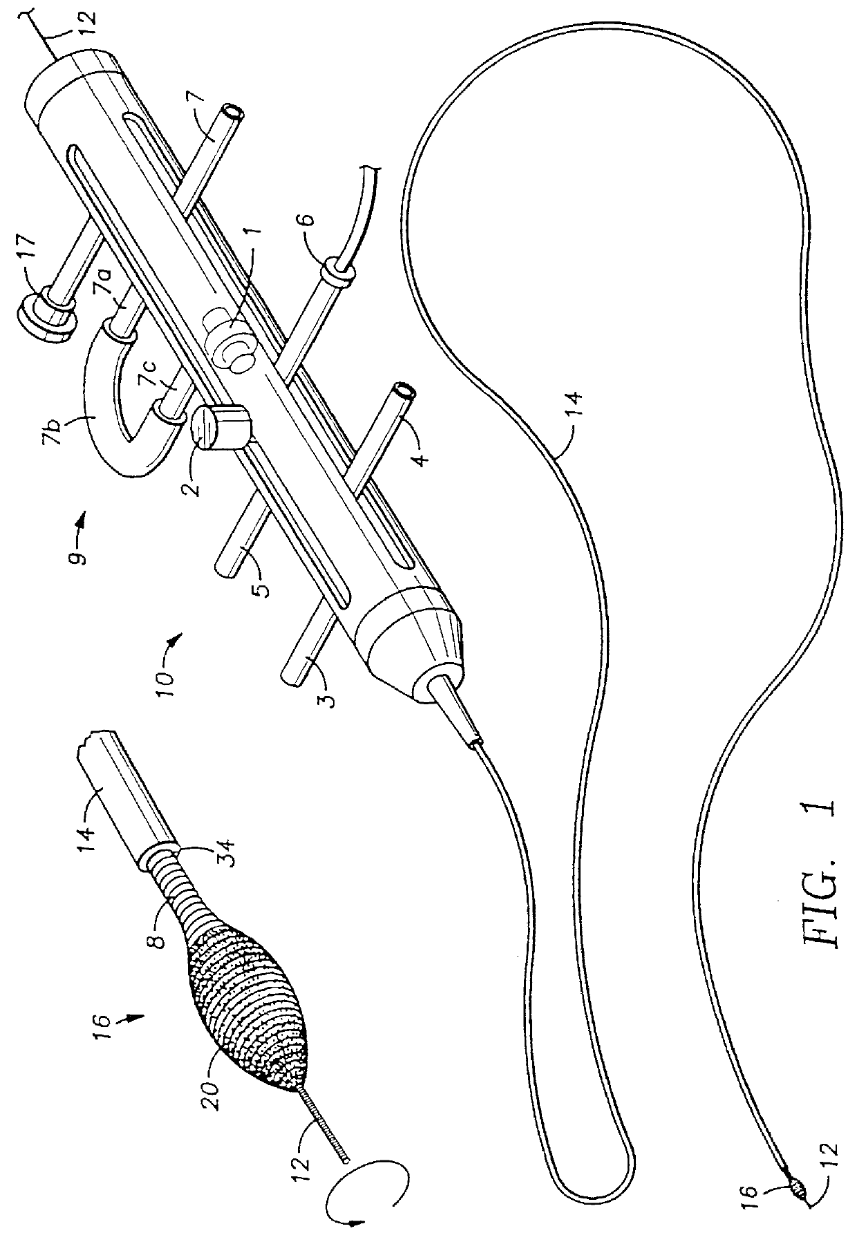
The drawings are illustrative of the apparatus of the present invention used for removing an obstruction from a vessel. The embodiments described are exemplary only, and can be modified in the practice of the invention.

FIG. 1 is a schematic representation of one type of system 10 adapted for use with some of the preferred embodiments of the adjustable tip atherectomy device of the invention. A drive-control unit 9 is attached to one end of a flexible catheter 14 which surrounds a drive shaft coil 8. Drive shaft coil 8 is adapted for high speed rotation within the catheter 14. Flexible catheter 14 is made of a suitable biocompatible material capable of withstanding the heat of friction generated when drive shaft coil 8 is rotated at high speed. Speeds of rotation of drive shaft coil 8 within flexible catheter 14 of about 100,000 to 300,000 revolutions per minute are contemplated for the present invention, which speeds may be generated, for example, by means of a conventional compress...


PUM


Abstract

A device for removing obstructions from vessels or small openings in the body, comprising a rotatable ablator tip which is guided to the obstruction in a reduced diameter configuration, expanded and rotated to remove the obstruction, and contracted to remove the device from the body. The variably expandable abrasive tip coil in one embodiment of the invention is actuated by a piston means disposed within the coil. A pair of collars is attached to the ends of the coil, and the piston effects relative longitudinal axial movement of the collars and, hence, the respective ends of the coil tip. When the ends of the coil tip are so moved with respect to one another, expansion and contraction of the diameter of the coil tip results. In another embodiment of the invention, the expansion tip coil is actuated by an expandable and contractible bellows means disposed within the coil, instead of the piston means. In another embodiment of the invention, the expansion and contraction of the coil tip are effected by longitudinal axial movement of an internal coil attached to one end of the coil tip, within an outer coil attached to the other end of the coil tip. In another embodiment of the invention, expansion and contraction of the coil tip are effected by an inflatable balloon disposed within the coil tip. The balloon expansion means enlarges preferably at the central portion of the coil to make a bulge. +RR The questions raised in reexamination request No. 90 / 003,360, filed Mar. 15, 1994, and 90 / 003,723 filed Feb. 14, 1995, have been considered and the results thereof are reflected in this reissue patent which constitutes the reexamination certificate required by 35 U.S.C. 307 as provided in 37 CFR 1.570(e).

Description

BACKGROUND OF THE INVENTION1. Field of the InventionThe present invention relates in general to devices for removing obstructions from vessels or small openings in the body, and more particularly to a rotatable ablator tip which is guided to the obstruction in a reduced diameter configuration, expanded and rotated to remove the obstruction, and contracted to remove the device from the body.2. Background ArtThere has been great interest of late among those in the medical community in non-surgical means to remove obstructions from occluded vessels, particularly coronary arteries. Traditionally, patients have had to undergo relatively complex, invasive, and risky coronary bypass surgery in order to obviate or reduce the obvious health hazards presented by occluded coronary arteries. Coronary bypass surgery typically involves utilizing vascular tissue from another part of the patient's body, such as his leg, and constructing a shunt around the obstructed vessel. The obstruction can be f...

Claims


Application Information

Patent Timeline
Patent Type & Authority Patents(United States)
IPC IPC(8): A61B17/32A61B17/00A61B17/22
CPCA61B17/22A61B17/320725A61B2017/00553A61B2017/22062A61B2017/22082A61B2017/22092A61B2017/320004
Inventor ZACCA, NADIM M.JASSO, MARTIN R.
Owner ZACCA NADIM M
Why Eureka
Try Eureka