
Annuloplasty procedures, related devices and methods

a technology of annuloplasty and related devices, applied in the field of annuloplasty techniques and devices, can solve the problems of limiting drawbacks of the cerclage technique or other indwelling coronary sinus prostheses, affecting and reducing the circumference so as to inhibit the application of pressure and improve the function of the mitral valve in the patient. , the effect of reducing the circumferen

Active Publication Date: 2018-04-12
TRANSMURAL SYST LLC +1
View PDF0 Cites 39 Cited by
  • Summary
  • Abstract
  • Description
  • Claims
  • Application Information

AI Technical Summary

Benefits of technology

The patent describes devices and methods to protect the heart's underlying structures from being compressed during a heart surgery called trans-sinus mitral annuloplasty. The devices include a sterile bridge that is placed within the coronary sinus to support a tensioning element used in constricting the mitral valve. The bridge prevents the tensioning element from applying pressure to the coronary artery and improves the function of the heart without affecting blood flow. The patent also describes the placement of the bridge within the coronary sinus using various techniques such as a groove or slot in the bridge or a tubular member attached to the bridge. Compressive forces are applied to the mitral valve to alter its shape and reduce its size while maintaining systemic blood flow.

Problems solved by technology

Trans-sinus approaches that use the cerclage technique or other indwelling coronary sinus prostheses can have limiting drawbacks, however, because the coronary sinus and its branches have now been found to cross the outer diameter of major coronary arteries in a majority of humans.
As a result, pressure applied by any prosthetic device in the coronary sinus (such as tension on the annuloplasty device) can compress the underlying coronary artery and induce myocardial ischemia or infarction.
In a majority of humans, the coronary vein crosses over the left circumflex artery, which has limited the usefulness of coronary sinus annuloplasty.

Method used


Image

  • Annuloplasty procedures, related devices and methods
  • Annuloplasty procedures, related devices and methods
  • Annuloplasty procedures, related devices and methods

Examples


third embodiment

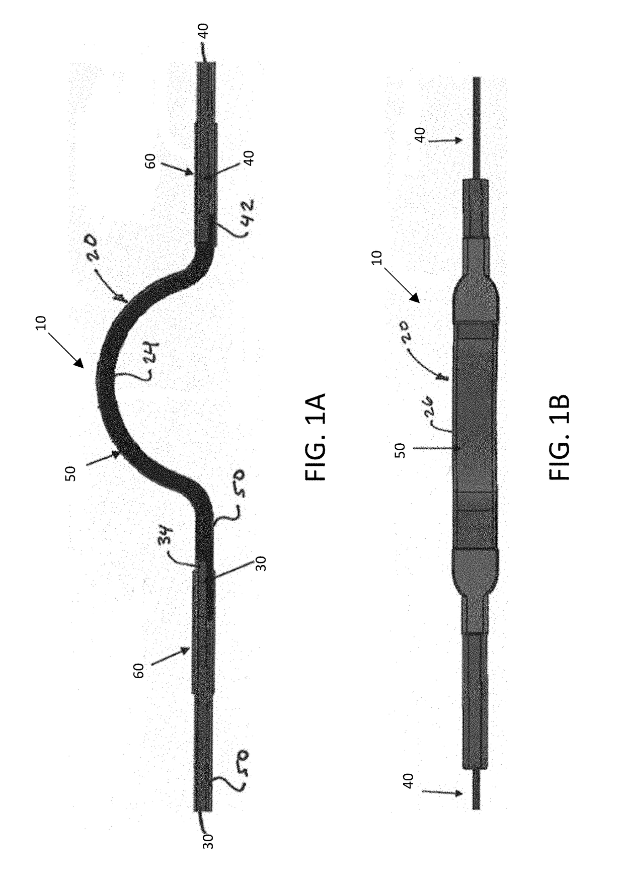
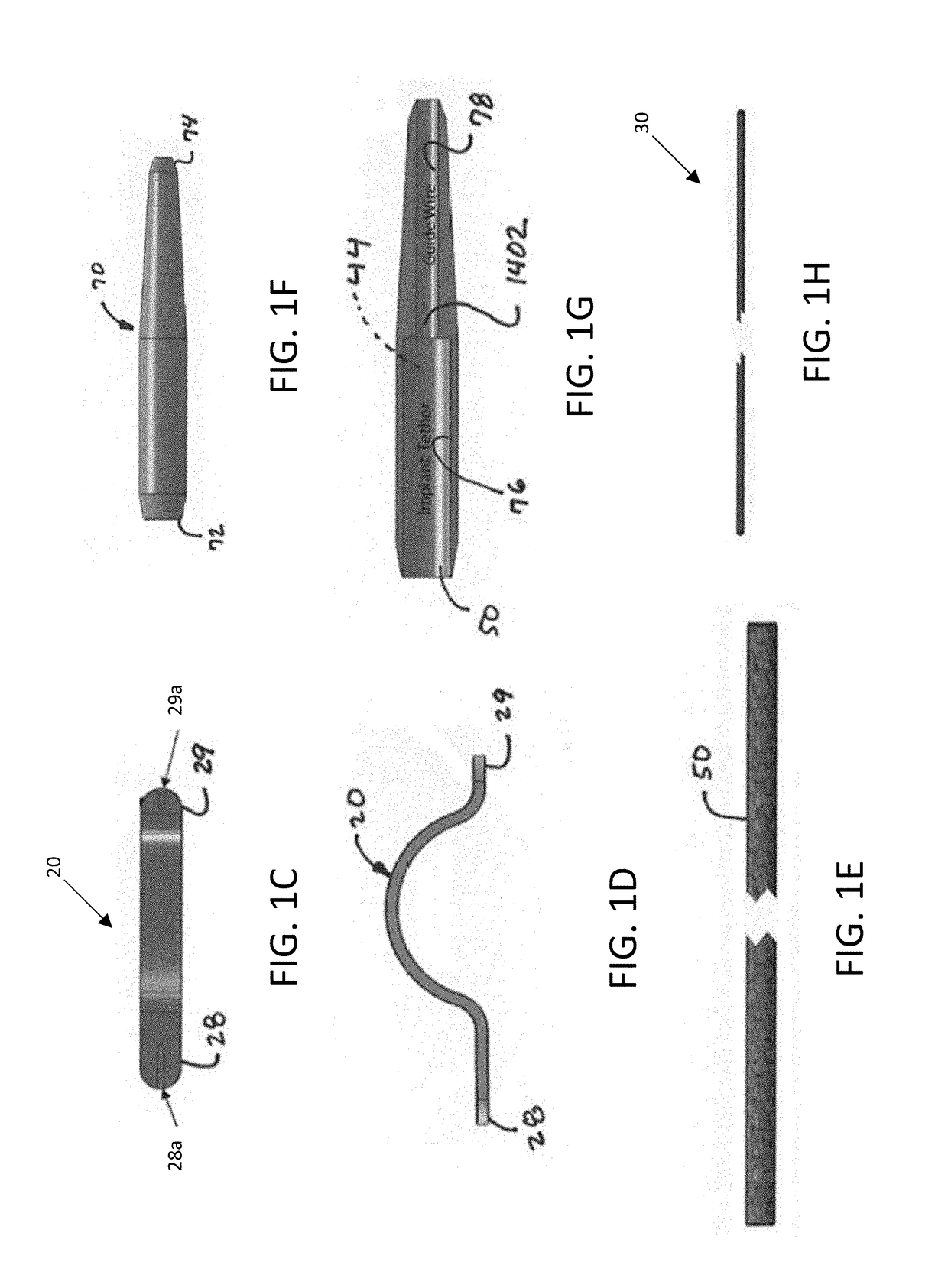
[0096]FIG. 1O illustrates a protection device, or bridge, 320 that may be used in the disclosed implants (e.g., 10, 210). Bridge 320 includes proximal and distal slots 328a, 329a at the proximal and distal ends 328, 329 of the bridge 320 for receiving welded hypotube lengths therein to in turn receive core wires 30, 40, therein for enhanced alignment and stability. Rather than slots with hypotube segments, holes can instead be bored into each end of the bridge 20 by way of electrical discharge machining (“EDM”) techniques.

[0097]FIG. 1P illustrates yet another embodiment of an implant 410 that includes a protection bridge 420 having proximal and distal extensions 428b, 429b extending outwardly from proximal and distal regions 428, 429 of the bridge 420. Proximal extension 428b is in turn received by a distal end sleeve 432b of proximal core wire 430, and proximal extension 429b is similarly received by a proximal end sleeve 442b of distal core wire 440. Core wires 430, 440 are provid...

fifth embodiment

[0099]As illustrated in FIG. 1W, with respect to the fifth embodiment, a side view of the protection element is provided, and an isometric view is provided in FIG. 1AK, wherein the (preferably radiopaque) tether is threaded through the holes of the protection element during assembly. As presented, the tether is threaded over the arch, and underneath the seating portions / ends of the protection element. As shown in FIG. 1X, which presents a further side view of the protection element and tether, if desired, a cover is applied over the combination of the tether and protection element, such as a tube of heat shrinkable material, a wound thread, or tubular fabric material. In the illustration, a tube of heat shrinkable PTFE is applied to the structure, thereby holding the relative positions of the tether and the protection element. FIG. 1Y presents a top view of the assembly of FIG. 1W, illustrating routing of the tether over the top of the arch of the protection element, whereas FIG. 1Z...

sixth embodiment

[0100]As illustrated in FIG. 1AA, with respect to the sixth embodiment, a side view of the protection element is provided, and an isometric view is provided in FIG. 1AL, wherein the tether is threaded through the holes of the protection element during assembly. As presented, the tether is threaded over the arch, and underneath the seating portions / ends of the protection element. As shown in FIG. 1AB, which presents a further side view of the protection element and tether, if desired, a cover is applied over the combination of the tether and protection element, such as a tube of heat shrinkable material, a wound thread, or tubular fabric material. In the illustration, a tube of heat shrinkable PTFE is applied to the structure, thereby holding the relative positions of the tether and the protection element. FIG. 1AC presents a top view of the assembly of FIG. 1AA, illustrating routing of the tether over the top of the arch of the protection element, whereas FIG. AD illustrates routing...


PUM


Abstract

Devices and methods are disclosed for the treatment or repair of regurgitant cardiac valves, such as a mitral valve. An illustrative annuloplasty device can be placed in the coronary sinus to reshape the mitral valve and reduce mitral valve regurgitation. An improved protective device can be placed between the annuloplasty device and an underlying coronary artery to inhibit compression of the underlying coronary artery by the annuloplasty device in the coronary sinus. In addition, the protective device can inhibit compression of the coronary artery from inside the heart, such as from a prosthetic mitral valve that exerts radially outward pressure toward the coronary artery. The annuloplasty device can also create an artificial inner ridge or retaining feature projecting into the native mitral valve region to help secure a prosthetic mitral valve.

Description

CROSS-REFERENCE TO RELATED APPLICATIONS[0001]The present patent application is a continuation-in-part of and claims the benefit of priority to International Application No. PCT / US2017 / 031543, filed May 8, 2017, which in turn claims the benefit of priority to U.S. Provisional Patent Application Ser. No. 62 / 332,754, filed May 6, 2016. The disclosure of each of the foregoing patent applications is expressly incorporated by reference herein for any purpose whatsoever.FIELD OF THE DISCLOSURE[0002]The present disclosure relates to annuloplasty techniques and devices in which tensioning elements (e.g., tethers) are placed in the coronary sinus to perform mitral valve annuloplasty and treat mitral valve regurgitation.BACKGROUND[0003]Mitral valve regurgitation is a common cardiac valve disorder that can be caused by a primary valvular problem (such as damaged valve leaflets) or functional problems that impair leaflet coaptation. A common cause of functional mitral valve regurgitation is dila...

Claims


Application Information

Patent Timeline
Patent Type & Authority Applications(United States)
IPC IPC(8): A61F2/24A61M25/01
CPCA61F2/2451A61F2/2466A61M25/01A61F2230/0045A61B17/320016A61F2250/0065A61B17/0467A61B17/3201A61M2025/0175A61B17/0487A61B2017/00358A61B2017/0496A61B17/221
Inventor RAFIEE, NASSERMACDONALD, STUARTRAFIEE, KOOSHABUSOLD, RANYLEDERMAN, ROBERT J.TOBY, ROGERS
Owner TRANSMURAL SYST LLC
Learn More