Vehicle driving apparatus

a technology for driving apparatuses and vehicles, applied in the direction of mechanical actuators, hybrid vehicles, electric devices, etc., can solve the problems of difficult to satisfy incompatible requirements at the same time, difficult to improve the axial support precision of the rotor and torque transmission capacity, and disclose the method of disposing of the support member, so as to achieve the effect of suppressing the increase in the overall axial direction length of the vehicle driving apparatus

Inactive Publication Date: 2012-09-27
AISIN AW CO LTD +1
View PDF7 Cites 37 Cited by
  • Summary
  • Abstract
  • Description
  • Claims
  • Application Information

AI Technical Summary

Benefits of technology

[0047]According to the fourteenth aspect, the space on the radial direction inner side of the rotor can be used effectively to dispose the fourth projecti...

Problems solved by technology

However, with the technique described in Japanese Patent Application Publication No. 2000-085386, the support member of the rotor is coupled to be capable of transmitting torque and axially aligned in a single coupling portion between the hub of the input shaft and the rotor support member, and it is therefore difficult to improve an axial support precision of the rotor and a torque transmission capacity simultaneously.
Hence, an improvement in the axial support precision of the ro...

Method used


Image

  • Vehicle driving apparatus
  • Vehicle driving apparatus
  • Vehicle driving apparatus

Examples


first embodiment

1. First Embodiment

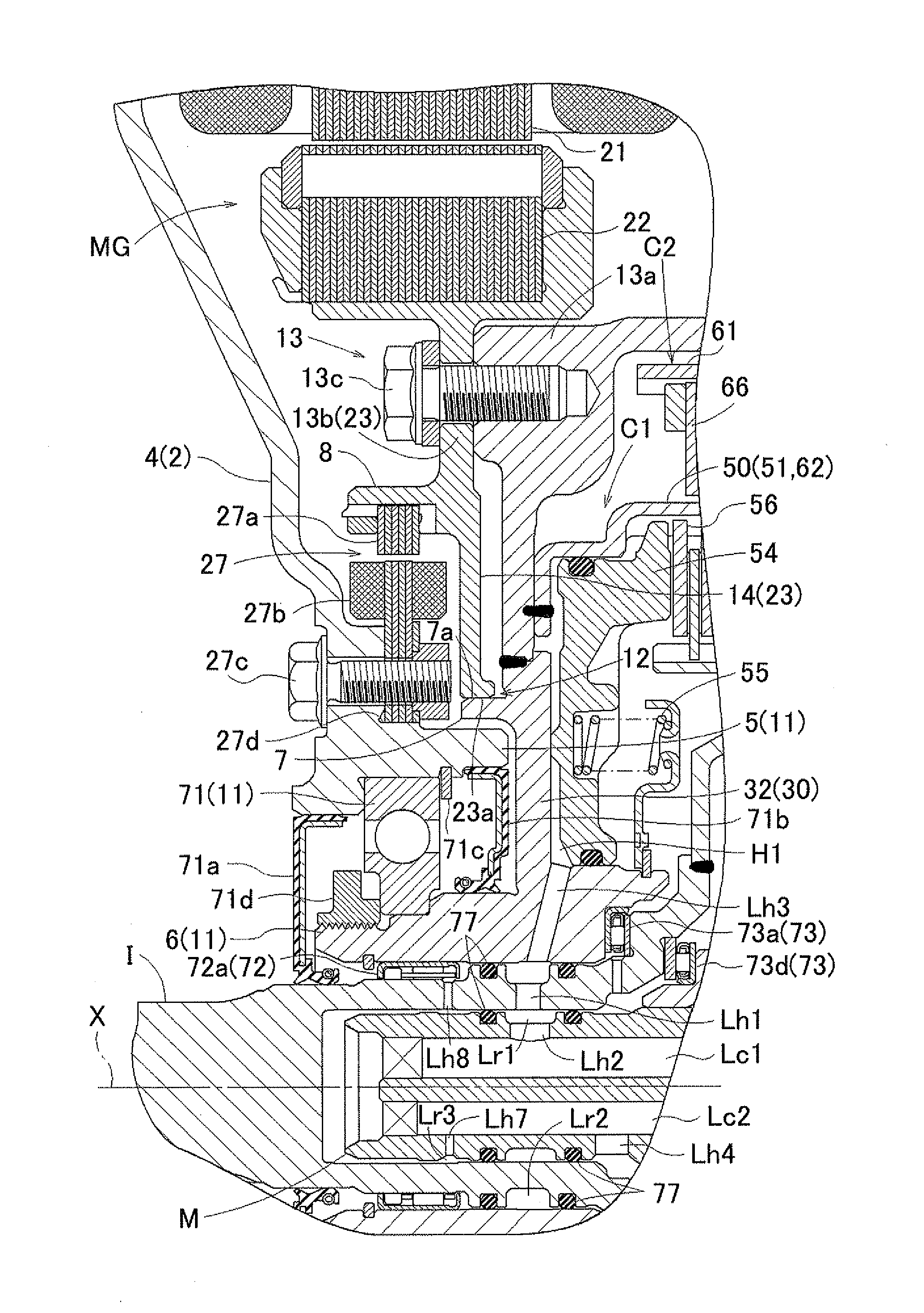
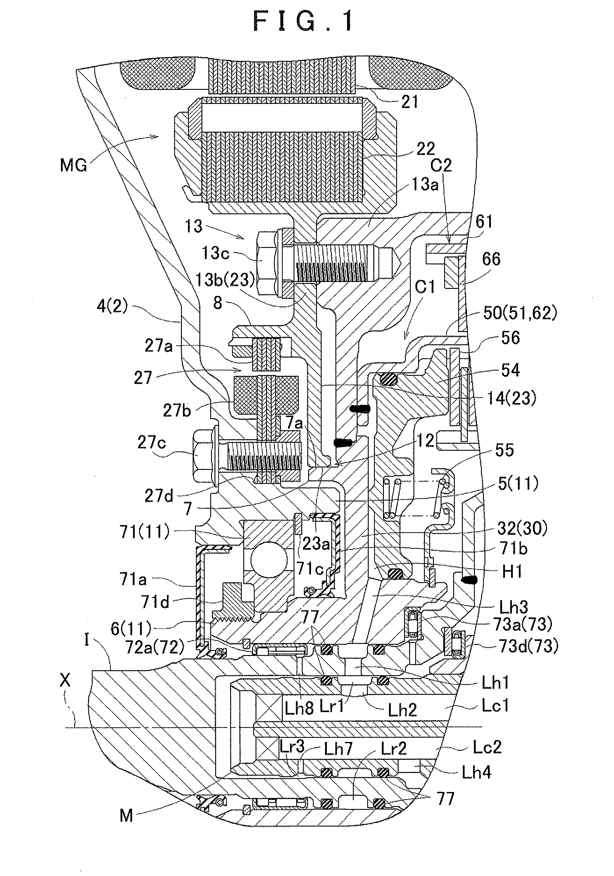
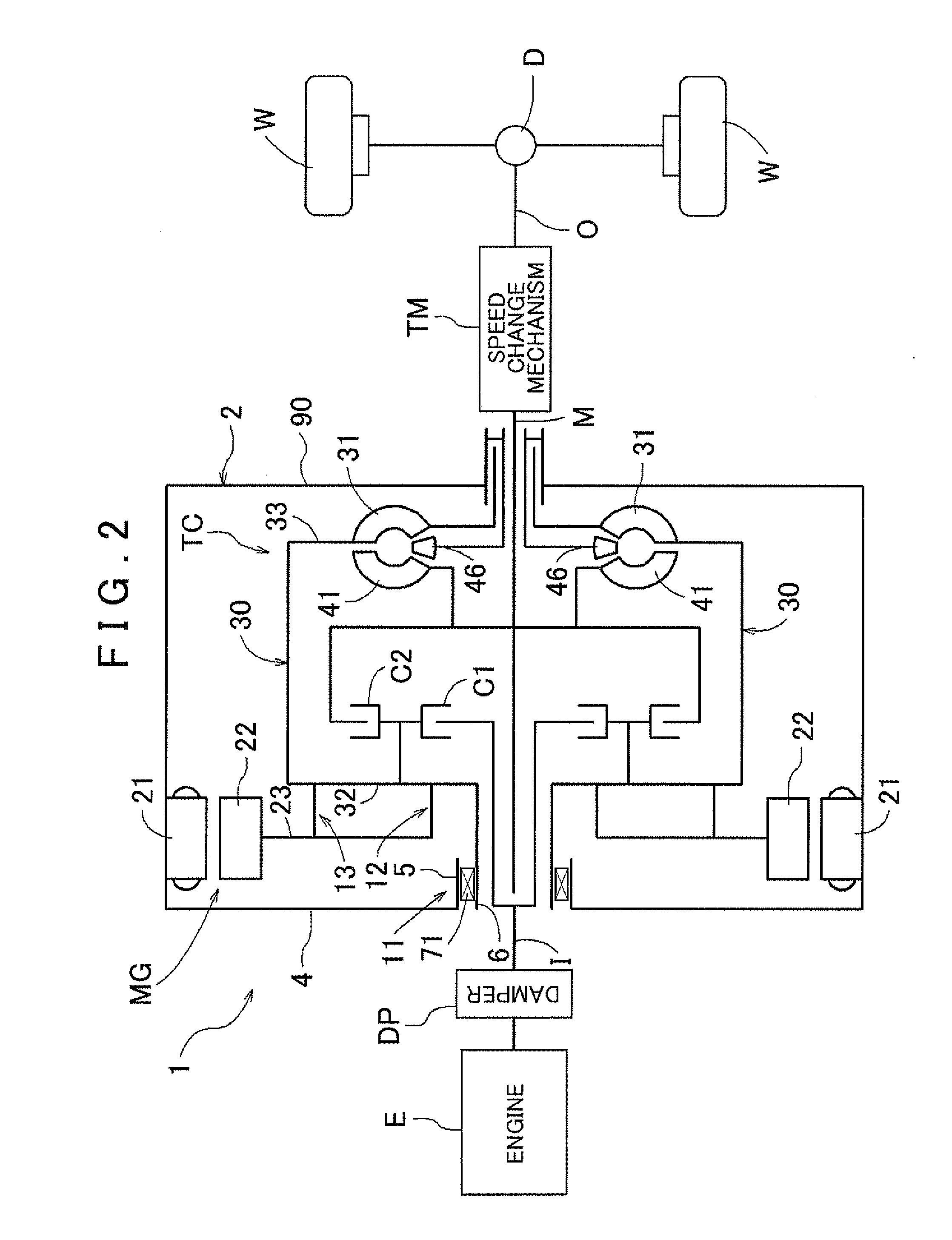
[0052]A first embodiment of the present invention will be described on the basis of the drawings. In this embodiment, a case in which a vehicle driving apparatus according to the present invention is applied to a hybrid driving apparatus 1 will be described as an example. The hybrid driving apparatus 1 is a driving apparatus for a hybrid vehicle that uses one or both of an engine E and a rotating electrical machine MG as vehicle drive power sources. As shown in FIG. 3, the hybrid driving apparatus 1 includes the rotating electrical machine MG which has a rotor 22 that rotates about an axial center X, a torque converter TC that serves as a power transmission device to which drive power from the engine E and the rotating electrical machine MG is transmitted, and a driving apparatus case 2 (to be referred to simply as a “case 2” hereafter) housing the rotating electrical machine MG and the torque converter TC. Note that in the following description, unless otherwise ...

second embodiment

2. Second Embodiment

[0117]A second embodiment of the present invention will now be described on the basis of the drawings. Likewise in this embodiment, a case in which the vehicle driving apparatus according to the present invention is applied to the hybrid driving apparatus 1 will be described as an example. The overall constitution and the constitutions of the respective parts of the hybrid driving apparatus 1 according to this embodiment are basically identical to those of the first embodiment described above. In this embodiment, however, as shown in FIG. 4, a radial direction arrangement of the first projecting portion 5 formed on the support wall 4 and the second projecting portion 6 formed on the front cover member 32 on either side of the support bearing 71 is reversed relative to the first embodiment. Accordingly, a fifth projecting portion 9 is provided anew to fix the rotation sensor 27 to the support wall 4. The arrangement of the oil seals 71a, 71b is also modified. The ...


PUM


Abstract

In a vehicle driving apparatus including a rotating electrical machine having a rotor and a case housing a power transmission device, a second projecting portion formed on a front cover member of the power transmission device is supported rotatably relative to a first projecting portion formed on a support wall of the case via a support bearing, a positioning fitting portion is provided to position a rotor support member for supporting the rotor relative to the front cover member in the radial direction, a torque transmitting coupling portion is provided on a radial direction outer side of the positioning fitting portion to couple the rotor support member and the front cover member so as to be capable of transmitting torque, and the positioning fitting portion and the torque transmitting coupling portion are respectively disposed to overlap a rotary support portion in an axial direction.

Description

INCORPORATION BY REFERENCE[0001]The disclosure of Japanese Patent Application No. 2009-288133 filed on Dec. 18, 2009 including the specification, drawings and abstract is incorporated herein by reference in its entirety.BACKGROUND OF THE INVENTION[0002]The present invention relates to a vehicle driving apparatus having at least two types of drive power sources, such as a rotating electrical machine and an engine, wherein drive power output by at least the rotating electrical machine is output via a power transmission device such as a torque converter.DESCRIPTION OF THE RELATED ART[0003]A vehicle installed not only with an engine (an internal combustion engine), which is used typically as a drive power source for vehicles such as automobiles, but also with a rotating electrical machine serving as a second drive power source has been developed in the related art. In this type of vehicle, the rotating electrical machine is used as a motor / generator. The rotating electrical machine outp...

Claims


Application Information

Patent Timeline
IPC IPC(8): H02K7/14H02K11/00
CPCB60K6/40B60K6/48F16D21/08F16D25/0638Y10T477/32Y02T10/6221B60K2006/4825Y02T10/6252H02K7/006B60L2220/50B60L50/16Y02T10/62Y02T10/64Y02T10/7072B60K2006/4833Y02T10/70
Inventor IWASE, MIKIOSUZUKI, TOMOHIDEOKISHIMA, TATSUYAKAMIYA, TOSHIHIKO
Owner AISIN AW CO LTD
Why Eureka
Try Eureka