Shaft sealing structure of centrifugal compressor

A centrifugal compressor and shaft sealing technology, which is applied to mechanical equipment, machines/engines, liquid fuel engines, etc., can solve the problems of cost increase, number of parts and installation man-hours, etc., and achieve the effect of shortening the length of the shaft direction

Active Publication Date: 2012-06-13
IHI ROTATING MACHINERY ENG CO LTD
View PDF3 Cites 0 Cited by
  • Summary
  • Abstract
  • Description
  • Claims
  • Application Information

AI Technical Summary

Problems solved by technology

[0007] However, the technique of Patent Document 3 constitutes a pressure equalizing hole passage module with a plurality of rings, so the number of parts and the man-hours for installation increase, and there is a problem that the cost increases.

Method used


Image

  • Shaft sealing structure of centrifugal compressor
  • Shaft sealing structure of centrifugal compressor
  • Shaft sealing structure of centrifugal compressor

Examples


no. 1 Embodiment approach

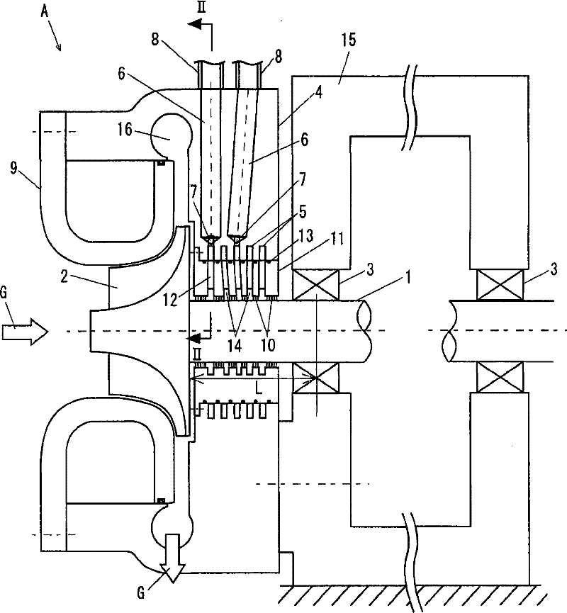
[0040] Figure 2 to Figure 7 It is a figure which shows the structure of the shaft seal structure A of the centrifugal compressor concerning 1st Embodiment of this invention.

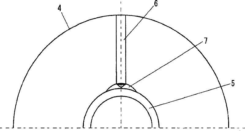
[0041]figure 2 , Figure 4 and Image 6 It is a cross-sectional view of the seal structure A in the axial direction, and shows cross-sections in phases different from each other in the circumferential direction. image 3 yes figure 2 The II-II line profile, Figure 5 yes Figure 4 Sectional view of line IV-IV, Figure 7 yes Image 6 Sectional view of line VI-VI. Among them, in image 3 , Figure 5 and Figure 7 In , only the housing 4 is shown.

[0042] exist figure 2 , Figure 4 and Image 6 Among them, the rotary shaft 1 is rotatably supported by a support bearing 3 fixed to a gear box 15 . The centrifugal impeller 2 is integrally connected to the tip of the rotary shaft 1, and the centrifugal impeller 2 is rotated by rotationally driving the rotary shaft 1 by a driving device not shown...

no. 2 Embodiment approach

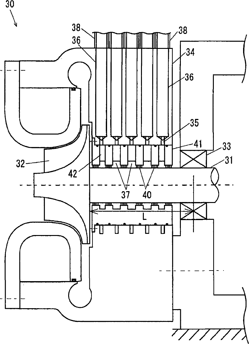
[0055] Figure 8 It is a sectional view in the axial direction showing the structure of the shaft seal structure B of the centrifugal compressor according to the second embodiment of the present invention. exist Figure 8 In , a cross-section of one phase in the circumferential direction is shown.

[0056] In the present embodiment, a plurality of ring-shaped equalizing pressure chambers corresponding to the spaces (seal chambers 14 ) between the plurality of labyrinth groups 10 are formed at intervals in the axial direction on the outer peripheral portion of the labyrinth ring 11 . Room 5. In the inner peripheral portion of the casing 4, a plurality of dug-in portions 7 that expand radially outward in a part of the outer peripheral portion of each pressure equalization chamber 5 in the circumferential direction are formed. Thus, the location where the pressure equalization chamber 5 is provided differs between this embodiment and the first embodiment.

[0057] exist Fig...

no. 3 Embodiment approach

[0060] Figure 9 It is a sectional view in the axial direction showing the structure of the shaft seal structure C of the centrifugal compressor according to the third embodiment of the present invention. exist Figure 9 In , a cross-section of one phase in the circumferential direction is shown.

[0061] In this embodiment, at the boundary portion between the housing 4 and the labyrinth ring 11, a plurality of annular grooves formed on the inner peripheral portion of the housing 4 and the labyrinth rings are formed at intervals in the axial direction. The ring-shaped pressure equalizing chamber 5 formed by the annular groove on the outer peripheral portion of 11. Each pressure equalization chamber 5 corresponds to a space (sealed chamber 14 ) between the plurality of labyrinth groups 10 . A plurality of dug-in portions 7 that expand radially outward in a part of the outer peripheral portion of each pressure equalization chamber 5 in the circumferential direction are formed...


PUM


Abstract

The present invention provides a shaft sealing structure of a centrifugal compressor, wherein a labyrinth ring (11) is supported at the inner circumstance of the casing (4). A plurality of labyrinth groups (10) are supported with an interval in the axial direction at the outer circumference of a rotating axis (1). The boundary part (such as the inner circumference of the casing (4)) between the casing and the labyrinth ring is formed with a plurality of annular equal-pressure chambers (5) with an interval in the axial direction. The casing (4) is formed with a plurality of digging-in parts (7) which enlarge the periphery part of each equal-pressure chamber (5) to the external of the radial direction at one part of the circumferential direction, and a plurality of drilling holes (6) which communicates each digging-in part with the external of the casing (4). Each group which is formed by digging-in part (7) and the drilling hole (6) is formed at the different phases of a plurality of circumferential directions to make that the groups do not interfere with one another.

Description

technical field [0001] The present invention relates to a shaft seal structure of a centrifugal compressor. Background technique [0002] Conventionally, in centrifugal compressors, in order to prevent leakage of compressed gas to the outside through the back side of the centrifugal impeller, a shaft seal structure is used to suppress gas flow in the axial direction between the rotating shaft and a stationary portion surrounding the rotating shaft. [0003] FIG. 1 is an axial cross-sectional view showing an example of a shaft seal structure 30 of a conventional centrifugal compressor. The annular labyrinth ring 41 is supported on the inner periphery of the housing 34 surrounding the rotary shaft 31 . A plurality of labyrinth groups 40 are supported at intervals in the axial direction on the outer peripheral portion of the rotating shaft 31 facing the labyrinth ring 41 . Each labyrinth group 40 is an aggregate of a plurality of fins. In the inner peripheral portion of the ...

Claims


Application Information

Patent Timeline
Patent Type & Authority Patents(China)
IPC IPC(8): F04D29/10
CPCF04D29/104
Inventor 河田真广若林拓也小野海士前田智久
Owner IHI ROTATING MACHINERY ENG CO LTD
Why Eureka
Try Eureka