Interspinous spacer assembly

a spacer and interstitial technology, applied in the field of orthopedics, to achieve the effect of preventing assembly migration

Active Publication Date: 2011-06-16
DEPUY SYNTHES PROD INC
View PDF14 Cites 212 Cited by
  • Summary
  • Abstract
  • Description
  • Claims
  • Application Information

AI Technical Summary

Benefits of technology

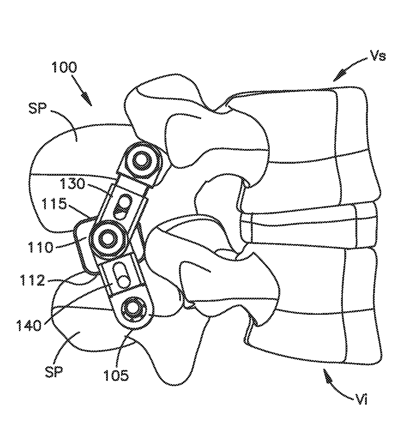
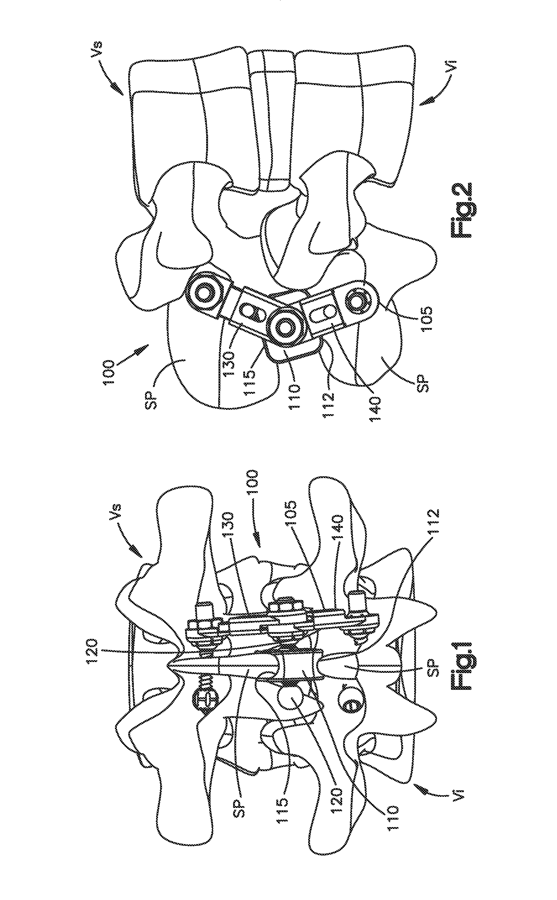
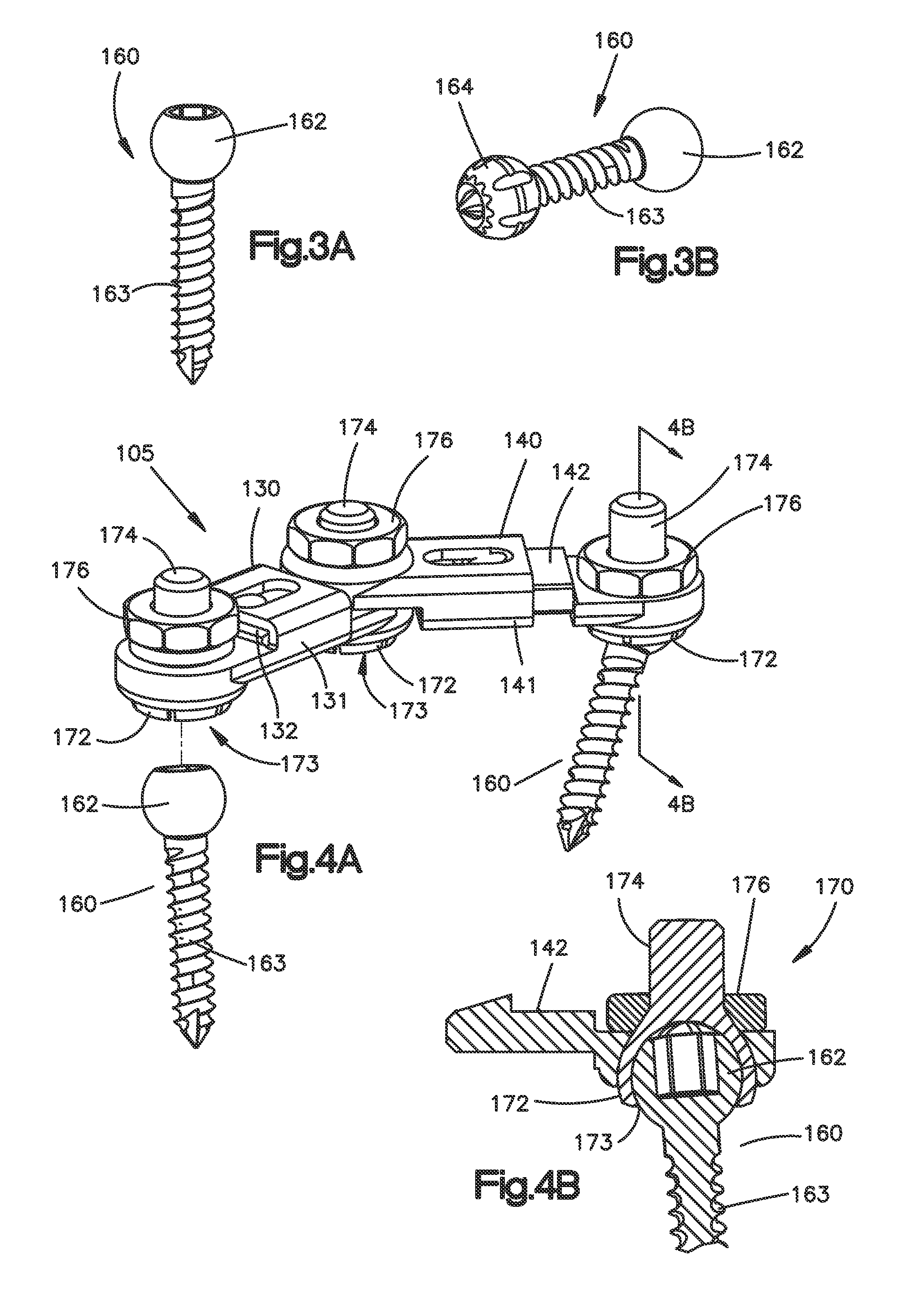
[0006]The present invention is directed to an interspinous spacer assembly for implantation and/or affixation between spinous processes of adjacent superior and inferior vertebrae. The interspinous spacer assembly preferably includes a spacer member sized and configured for insertion into the space between adjacent spinous processes

Problems solved by technology

This constricts the space in the spinal ca

Method used


Image

  • Interspinous spacer assembly
  • Interspinous spacer assembly
  • Interspinous spacer assembly

Examples


Embodiment Construction

[0064]Certain terminology is used in the following description for convenience only and is not limiting. The words “right”, “left”, “lower” and “upper” designate directions in the drawings to which reference is made. The words “inwardly” and “outwardly” refer to directions toward and away from, respectively, the geometric center of the interspinous spacer and designated parts thereof. The words “anterior”, “posterior”, “superior”, “inferior” and related words and / or phrases designate preferred positions and orientations in the human body to which reference is made and are not meant to be limiting. The words and phrases “collapse”, “telescopic”, “disposed within”, “slidably disposed within”, “interlock” and related words and / or phrases designate the relationship between two parts or devices to which reference is made and are not meant to limiting. The terminology includes the above-listed words, derivatives thereof and words of similar import.

[0065]Certain exemplary embodiments of th...


PUM


Abstract

An interspinous spacer assembly (100) for insertion and/or implantation between spinous processes of adjacent superior and inferior vertebrae includes an interspinous spacer member (110) sized and configured for insertion into the interspinous space located between adjacent spinous processes and an engagement mechanism (105) for operatively coupling the spacer member to the adjacent spinous processes and for preventing migration of the assembly once implanted. The interspinous spacer assembly is adjustable to conform to the individual anatomy of a patient's spine.

Description

CROSS REFERENCE TO RELATED APPLICATIONS[0001]This application claims priority to U.S. Provisional Patent Application No. 61 / 088,574, filed Aug. 13, 2008, entitled “POSTERIOR STABILIZATION DEVICE,” the contents of which are hereby incorporated by reference in its entirety.FIELD OF THE INVENTION[0002]The present invention relates generally to orthopedics. More specifically, the present invention relates to an interspinous spacer assembly and associated methods for stabilizing the human spine.BACKGROUND OF THE INVENTION[0003]A human vertebra has a rearwardly projecting portion known as a spinous process. Bending or the natural aging and degeneration of the spine can cause the spinous processes of adjacent vertebrae to be moved toward each other. This constricts the space in the spinal canal and foramina and, thus, may cause pain. Such constriction, known as stenosis, can be treated by the use of an implant in the space between adjacent spinous processes.[0004]Generally speaking there a...

Claims


Application Information

Patent Timeline
IPC IPC(8): A61B17/70
CPCA61B17/025A61B17/7052A61B17/7053A61B17/8695A61B17/7068A61B17/8605A61B17/8665A61B17/7065A61B17/70A61B17/86A61B17/88A61F2/44A61B17/7047A61B17/7056A61B17/7067
Inventor SALADIN, STEFANASCHMANN, FELIXSCHAER, MANUELCOPPES, JUSTINANGERT, NICHOLASSKIDMORE, GRANTMAYER, MICHAEL
Owner DEPUY SYNTHES PROD INC
Why Eureka
Try Eureka