Actor node, sensor node, coverage block change method, parameter change method, program, and information processing system

a sensor node and node technology, applied in the field of sensor nodes, can solve the problems that both event handling and data collection cannot be achieved at the same tim

Inactive Publication Date: 2011-06-16
SONY CORP
View PDF5 Cites 32 Cited by
  • Summary
  • Abstract
  • Description
  • Claims
  • Application Information

AI Technical Summary

Benefits of technology

[0028]As explained above, according to the present invention, in a case where an actor node handles an unexpected event when an event occurs, coverage regions of actor nodes can be temporarily changed. As a result, another actor node can perform data collection from se

Problems solved by technology

However, methods described in “Hybrid Authentication and Key Management Scheme for WSANs” and “Key Establishment Between Heterogenous Nodes in Wireless Sensor and Actor Networks” relate to authenticati

Method used


Image

  • Actor node, sensor node, coverage block change method, parameter change method, program, and information processing system
  • Actor node, sensor node, coverage block change method, parameter change method, program, and information processing system
  • Actor node, sensor node, coverage block change method, parameter change method, program, and information processing system

Examples


first embodiment

[0079]First, an information processing system according to the first embodiment of the present invention will be explained in detail with reference to FIGS. 1 to 3. FIGS. 1 to 3 are explanatory diagrams for illustrating the information processing system according to the present embodiment.

[Overview of Information Processing System]

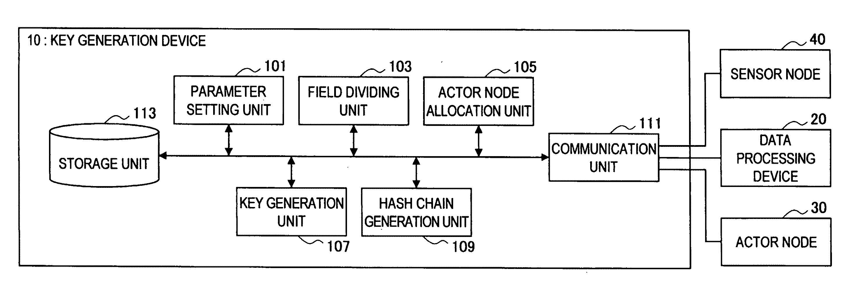
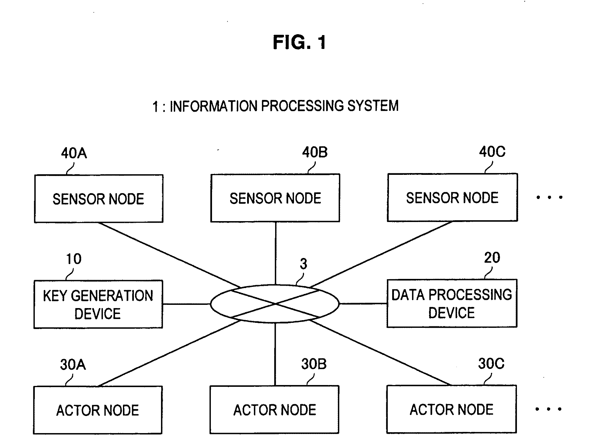
[0080]For example, as shown in FIG. 1, the information processing system 1 according to the embodiment includes a key generation device 10 and a data processing device 20. Further, the information processing system 1 includes actor nodes 30A, 30B, 30C . . . (hereinafter abbreviated as actor node 30) and sensor nodes 40A, 40B, 40C . . . (hereinafter abbreviated as sensor node 40). These devices are connected with each other via a network 3.

[0081]The communication network 3 is a communication circuit network for allowing bidirectional communication between the key generation device 10, the data processing device 20, the actor node 30, and the sensor node 40....

embodiments

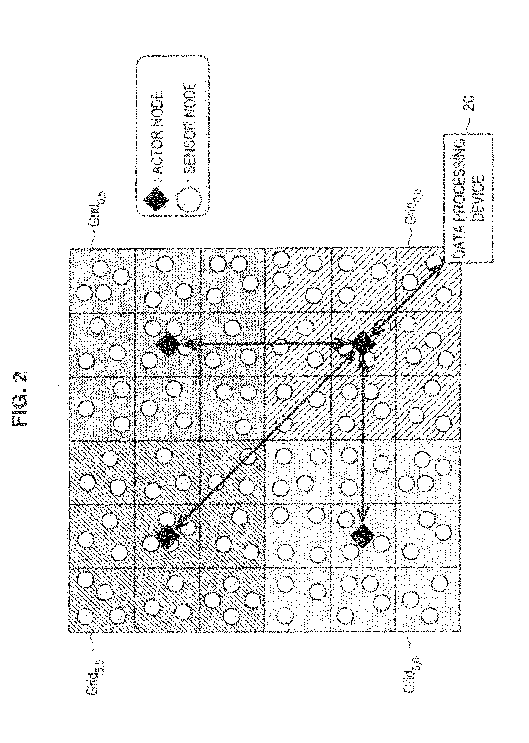
[0384]Subsequently, a specific example of dynamic change processing (processing performed with start of dynamic change) performed by the actor nodes and the sensor nodes will be explained with reference to FIGS. 21A and 21B.

[0385]In the below explanation, the following case will be considered. Coverage grids of an actor 1 to an actor 4 as shown in FIG. 21A in a normal state change to coverage grids as shown in FIG. 21B in response to a certain event. In the below explanation, the processing of the actor 1 will be briefly explained. The processings of the actor 2 to the actor 4 are also performed in the same manner as the below explanation.

[0386]In the normal state, the coverage grids of the actor 1 are nine grids G0,0 to G2,2 as shown in FIG. 21A. When these coverage grids are changed as shown in FIG. 21B in response to an event, it is understood that the grid G3,1 is covered by the actor 1, and the grid G0,2 is covered by the actor 3.

[0387]Accordingly, the dynamic change unit 313 o...


PUM


Abstract

An actor node according to the present invention includes a dynamic change unit for temporarily changing a coverage block in which data are obtained from a sensor node and temporarily causing another actor node to obtain, on behalf of the actor node, data from the sensor node arranged in a partial region of at least a portion of the coverage blocks. The dynamic change unit obtains identification information unique to the another actor node from the another actor node. The dynamic change unit notifies, to the sensor node arranged in the partial region, the obtained identification information. The dynamic change unit notifies, to the another actor node, a portion of the hash chain and a temporary key generated using the obtained identification information and the key used for communication with the sensor node arranged in the partial region.

Description

BACKGROUND OF THE INVENTION[0001]1. Field of the Invention[0002]The present invention relates to an actor node, a sensor node, a coverage block change method, a parameter change method, a program, and an information processing system.[0003]2. Description of the Related Art[0004]Wireless sensor network (WSN) has been studied for a long time. The wireless sensor network is a system for obtaining data from many sensor nodes arranged within a predetermined region and performing a predetermined processing based on the obtained data. Recently, a method using an actor node capable of moving in a network field has been used in order to easily obtain data from many sensor nodes. Such system using the actor node to collect data is called a wireless sensor and actor network (WSAN).[0005]This WSAN is a system used to achieve an object such as monitoring whether there is an intruder and preventing fire. When an event occurs that may cause failure of an object to be achieved, such as presence of ...

Claims


Application Information

Patent Timeline
IPC IPC(8): H04L9/32H04L9/08
CPCH04L9/0866H04L9/0891H04L9/3236H04L2209/805H04L63/06H04L63/08H04L2209/38H04L9/3273H04L9/50
Inventor ASANO, TOMOYUKIKUSAKAWA, MASAFUMICHOI, IMSUNG
Owner SONY CORP
Why Eureka
Try Eureka