Watercraft hull and associated methods

a technology for watercraft and hulls, applied in waterborne vessels, floating buildings, vessel construction, etc., can solve problems such as excessive angle of inclination, directionally unstable, and flat-bottomed planing hulls, and achieve the effect of minimal water resistan

Active Publication Date: 2011-06-23
VON LIGNAU ALEXANDER
View PDF19 Cites 2 Cited by
  • Summary
  • Abstract
  • Description
  • Claims
  • Application Information

AI Technical Summary

Benefits of technology

[0011]With the foregoing in mind, the present invention provides a watercraft hull that advantageously allows for minimal water resistance by virtue of a vacuum chamber. The watercraft hull according to the present invention also advantageously provides a tunnel for directional stability. The watercraft hull according to the present invention further advantageously provides a deep vee bow portion to permit an acceptable angle of inclination not susceptible to tail or head winds.

Problems solved by technology

Flat-bottomed planing hulls encounter minimal resistance with the water surface, but can be directionally unstable.
Tunnel hulls can also be directionally stable, but may have a tendency to have an excessive angle of inclination and can be susceptible to tail or head winds.
None of these historical watercraft hull shapes provides minimal water resistance together with directional stability and an acceptable angle of inclination not susceptible to tail or head winds.

Method used


Image

  • Watercraft hull and associated methods
  • Watercraft hull and associated methods
  • Watercraft hull and associated methods

Examples


Embodiment Construction

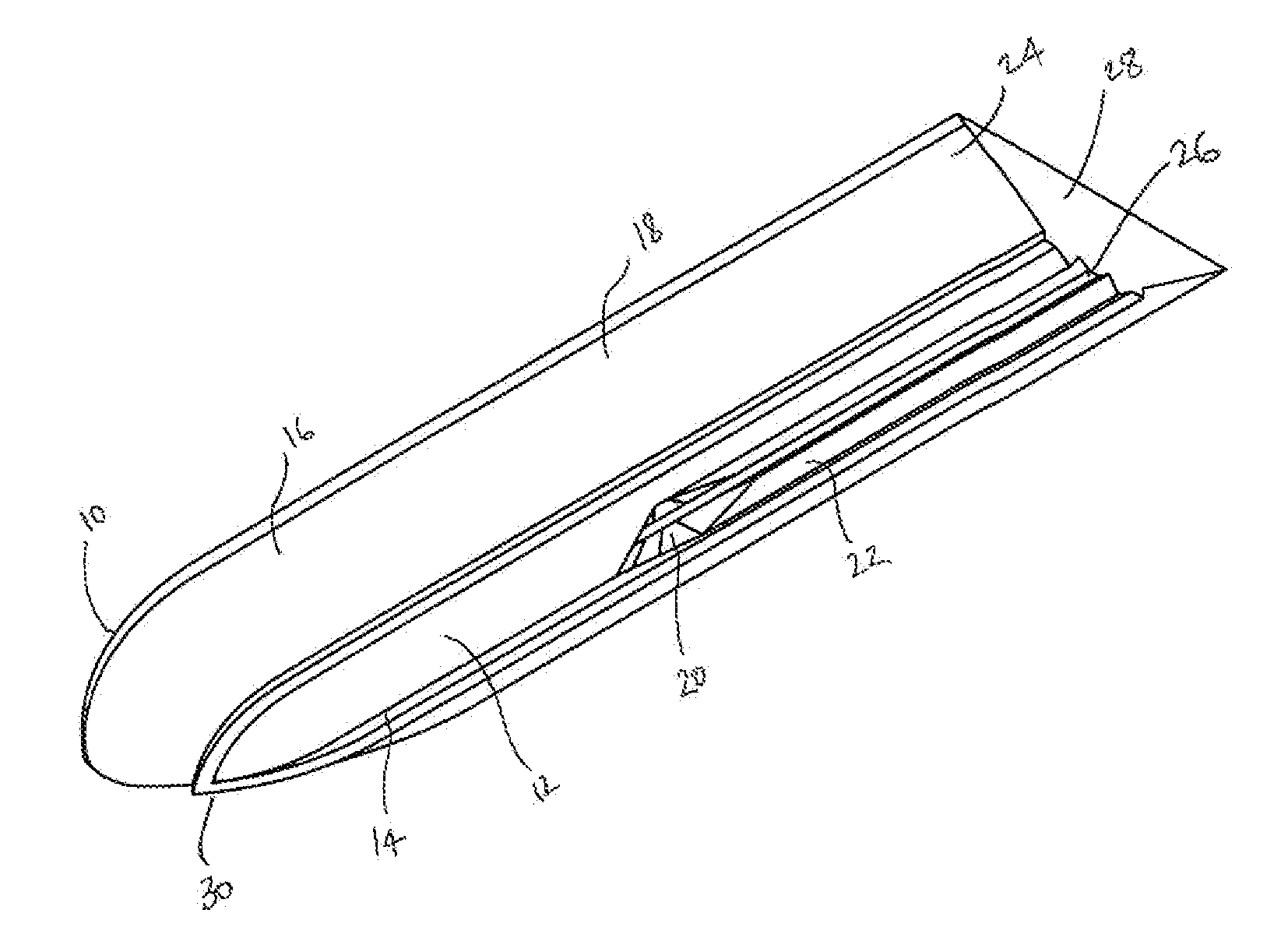
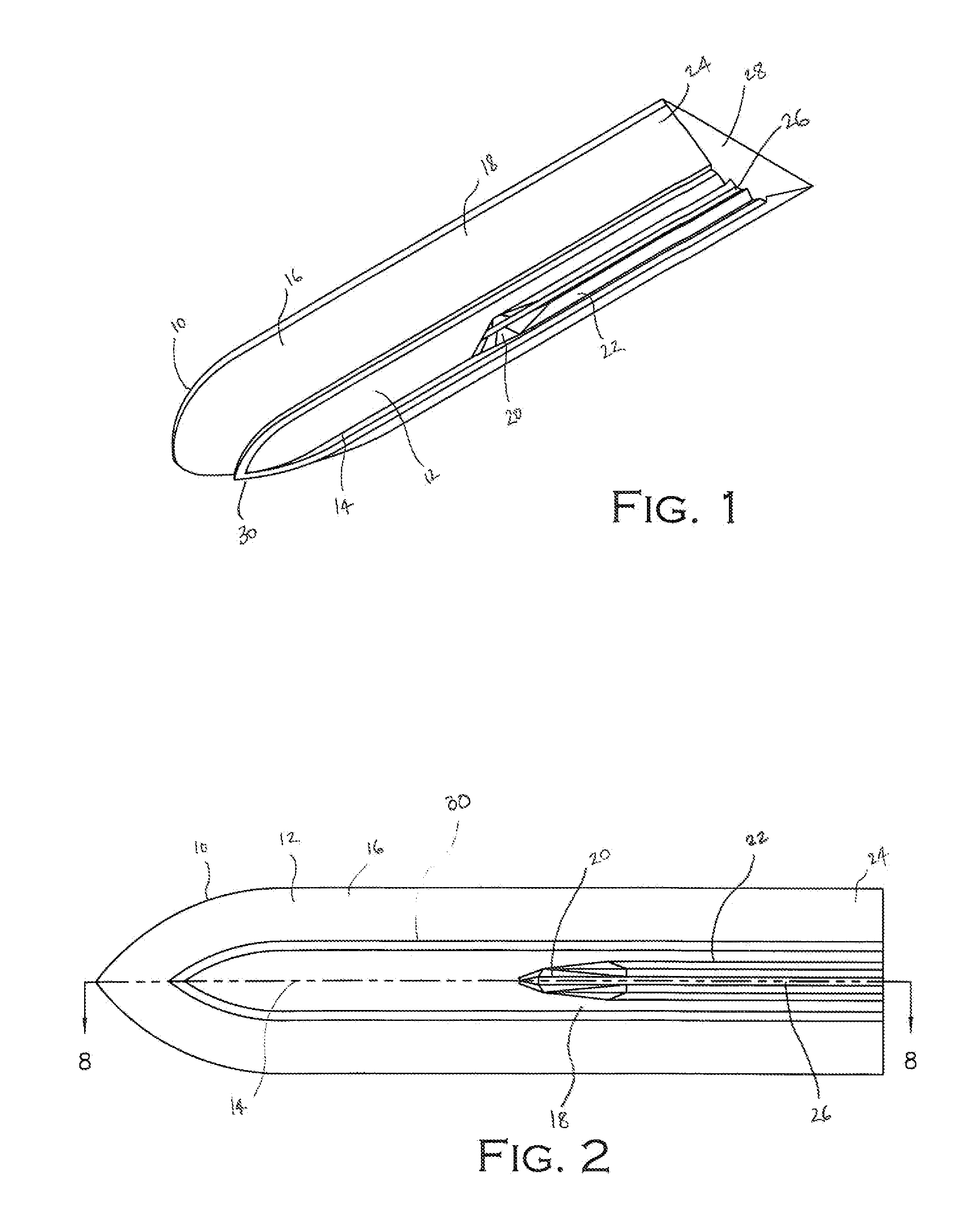
[0030]A watercraft using a watercraft hull 10 according to the present invention can advantageously achieve minimal water resistance, resulting in higher performance and improved fuel economy. The system according to the present invention also advantageously provides the watercraft hull 10 with greatly increased directional stability. The system according to the present invention further advantageously provides a watercraft hull 10 that achieves greater lift. The advantages of the system according to the present invention may be realized whether operating a watercraft having a completely newly fabricated watercraft hull 10 according to the present invention or operating a watercraft having a retrofitted watercraft hull 10 according to the present invention.

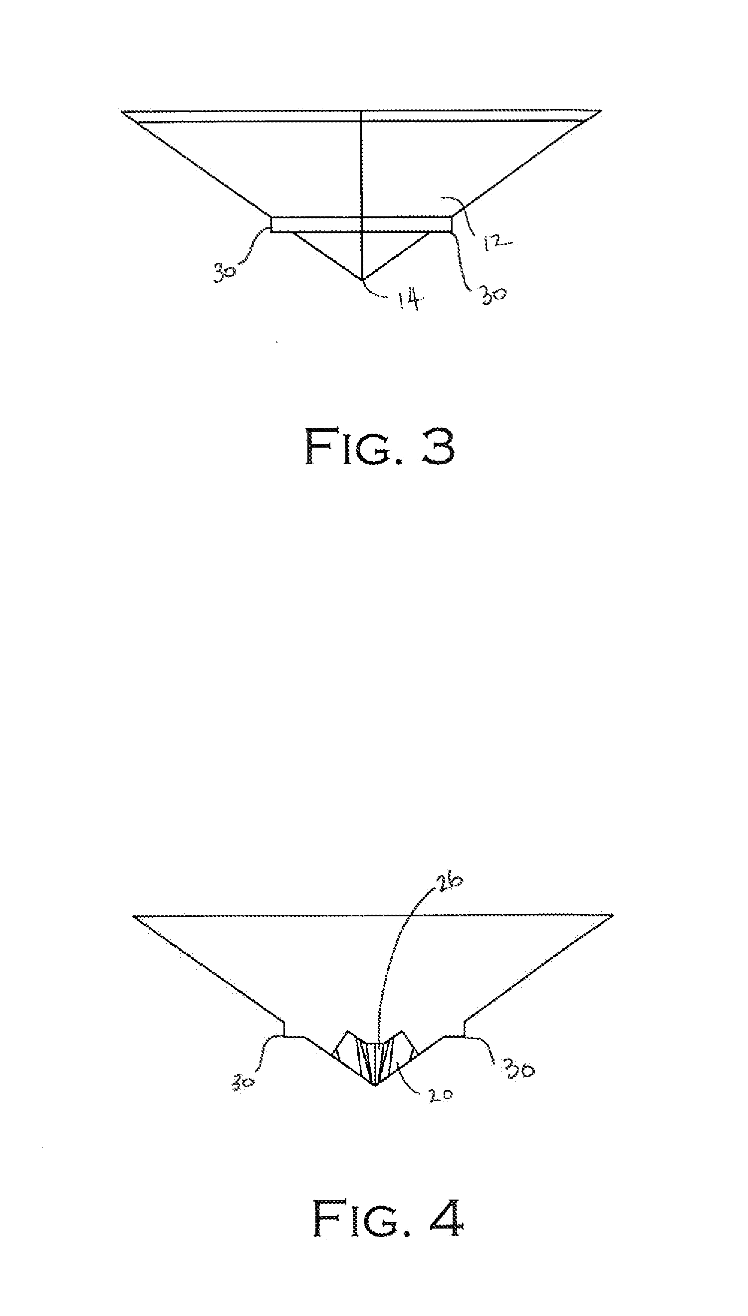
[0031]Referring now to FIGS. 1-9, details of the watercraft hull 10 according to the present invention are now described in greater detail. The watercraft hull 10 according to the present invention advantageously allows a user to ...


PUM


Abstract

A watercraft hull includes a lower portion, an upper portion, and a strake positioned between the lower portion and the upper portion. The lower portion may include a bow portion having a v-shape defined by a keel and sidewalls extending upwardly therefrom to the strake and an aft portion having a tunnel formed therein. The aft portion may be defined by a pair of opposing sidewalls extending downwardly from the strake to a bottom portion. The tunnel may be defined by a pair of opposing tunnel sidewalls that extend upwardly from the bottom portion to a tunnel top having a center rib. The lower portion may also include a medial portion that transitions the bow portion to the aft portion. The medial portion may have a vacuum chamber extending between and transitioning the keel of the bow portion to the tunnel formed in the aft portion.

Description

RELATED APPLICATIONS[0001]The present application claims the benefit of U.S. Provisional Patent Application Ser. No. 61 / 289,760 titled HIGH PRESSURE DEEP VEE TUNNEL HULL AND ASSOCIATED METHODS filed by the inventor of the present invention on Dec. 23, 2009, the entire contents of which are incorporated herein by reference.FIELD OF THE INVENTION[0002]The present invention relates to the field of watercraft hulls and, more specifically, to the field of watercraft hull shapes and associated methods.BACKGROUND OF THE INVENTION[0003]For as long as humans have piloted watercraft over bodies of water, humans have attempted to improve the design of their watercraft hulls. Historically, watercraft hulls have been in three well known classes: flat-bottomed planing hulls, deep vee hulls, and tunnel hulls. Each class of historical hull has associated with its shape certain advantages and certain disadvantages. Flat-bottomed planing hulls encounter minimal resistance with the water surface, but ...

Claims


Application Information

Patent Timeline
Patent Type & Authority Applications(United States)
IPC IPC(8): B63B1/06B63B1/08
CPCB63B1/04Y02T70/12B63B1/32Y02T70/10
Inventor VON LIGNAU, ALEXANDER
Owner VON LIGNAU ALEXANDER
Why Eureka
Try Eureka