
Ball head for camera tripod capable of finely adjusting front and rear angles through mechanical manipulation

a technology of mechanical manipulation and ball head, which is applied in the direction of machine supports, instruments, other domestic objects, etc., can solve the problems of difficult for users to fasten the ball, and the accurate adjustment of the desired photographing angle is significantly difficult, so as to achieve the effect of fine adjustment of the photographing angl

Inactive Publication Date: 2011-06-23
KANG PIL SIK
View PDF2 Cites 20 Cited by
  • Summary
  • Abstract
  • Description
  • Claims
  • Application Information

AI Technical Summary

Benefits of technology

[0008]As described above, after a photographing angle has been primarily adjusted, the fine adjustment of the photographing angle can be simply achieved through repeated mechanical manipulations. If the slider is used, the adjustment can be achieved in left and right directions as well as the front and rear directions.

Problems solved by technology

However, such a conventional ball head has disadvantages in that a user has to release the pressure applied to the ball by unfastening a knob and then finely adjust a photographing angle to a desired degree by using the hand when the fine adjustment of the photographing angle is required in a state that the heavy telescope lens or photographing appliances are mounted on the tripod after the photographing angle has been primarily adjusted by the hand of the user.
In this case, the accurate adjustment to a desired photographing angle is significantly difficult due to the heavy weight of the telephoto lens or the photographing appliances.
In particular, it is actually difficult for the user to fasten the ball by fastening the knob using one hand while supporting the telephoto lens or the photographing appliances using the other hand.

Method used


Image

  • Ball head for camera tripod capable of finely adjusting front and rear angles through mechanical manipulation
  • Ball head for camera tripod capable of finely adjusting front and rear angles through mechanical manipulation
  • Ball head for camera tripod capable of finely adjusting front and rear angles through mechanical manipulation

Examples


Embodiment Construction

[0015]Hereinafter, the present invention will be described in detail with reference to accompanying drawings.

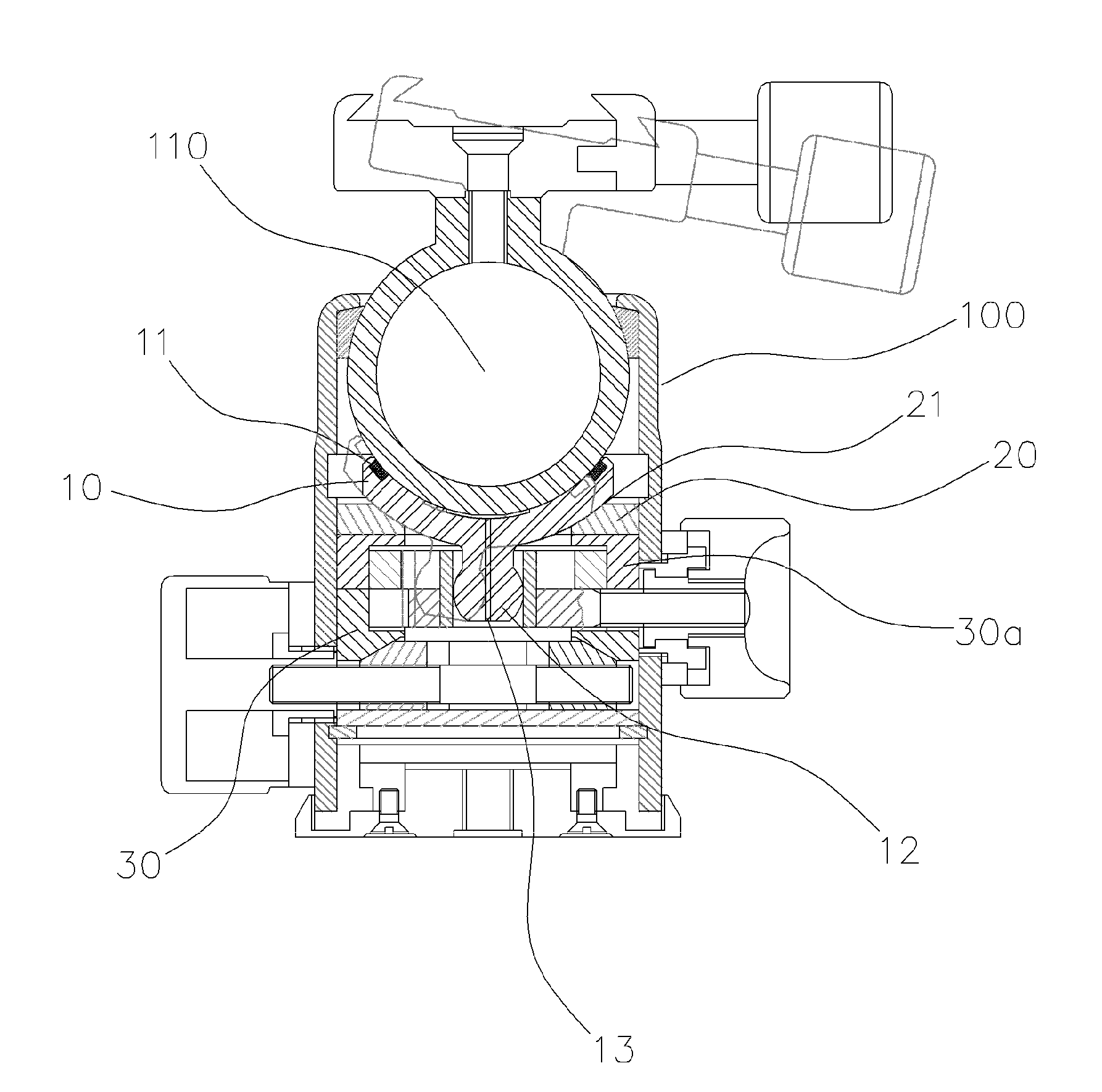
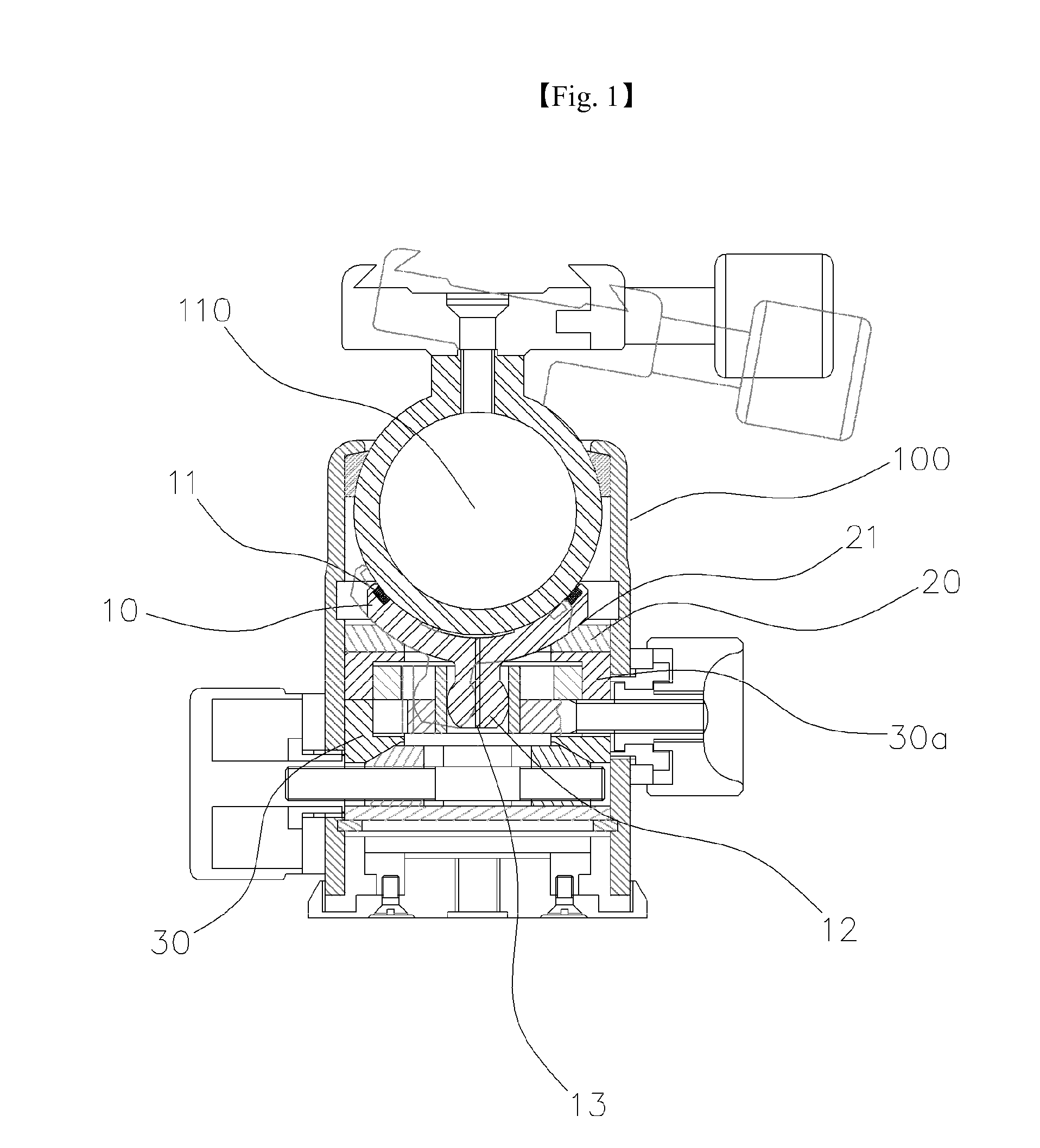
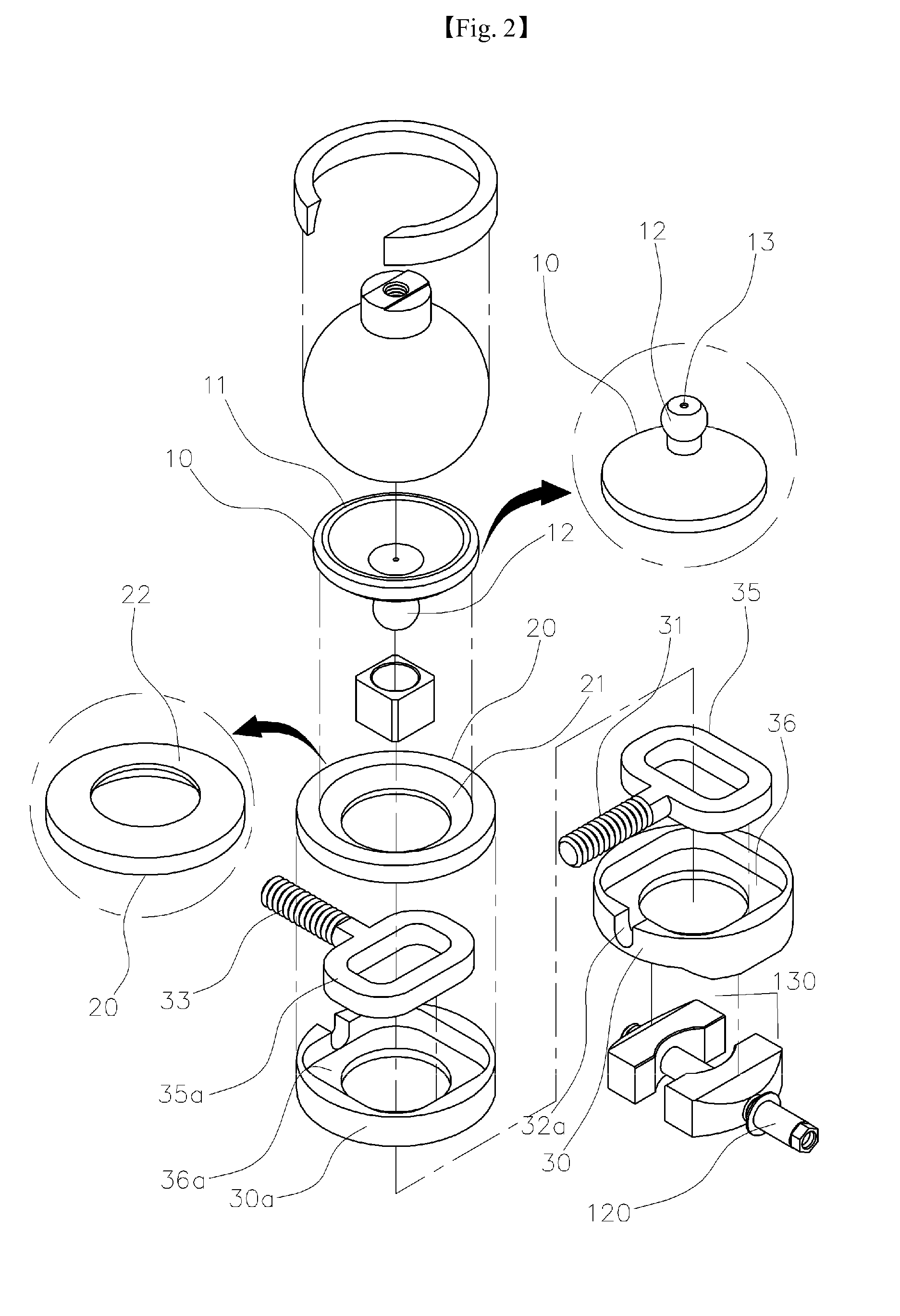
[0016]As shown in FIG. 1, according to the present invention, a ball guide 10 having a curved shape is provided under a ball 110 while closely adhering to the ball. In order to increase the fixing strength between the ball and the ball guide 10, a friction ring 11 protrudes from the rim of the ball guide 10 to the extent that the friction ring 11 may closely adhere to the ball. A shaft 12 protrudes directly downward from the central portion of the ball guide 10 and has a predetermined strength such that the shaft 12 is not bent when the shaft 12 is pushed or pulled in order to adjust the angle of the ball in front and rear directions. The ball guide 10 has a curved surface to closely adhere to the ball and is provided around the rim thereof with the friction ring 11, so that a vacuum occurs between the ball and the curved surface. In this case, the ball does not move when the...


PUM


Abstract

Disclosed is a ball head for a camera tripod. The movement of the ball head is finely adjusted in front, rear, left, and right directions through mechanical manipulation. Since a conventional ball head is mounted with a ball on a tripod, after a user releases the ball head from the pressure and freely adjusts the ball head in front, rear, left, and right directions by a hand, the user fastens a knob of fixing the ball to press the ball so that a lower plate of supporting the ball tightens the ball to fix the ball. Such a conventional ball head has disadvantages in that the user has to release the pressure applied to the ball by unfastening the knob and then finely adjust a photographing angle to a desired degree by using the hand when the repeated fine adjustment of the photographing angle is required in a state that the heavy telescope lens or photographing appliances is mounted on the tripod after the photographing angle has been primarily adjusted by the hand of the user. The accurate adjustment to a desired photographing angle is significantly difficult due to the heavy weight of the telephoto lens or the photographing appliances. The angle adjustment is repeatedly achieved through mechanical manipulation.

Description

TECHNICAL FIELD[0001]The present invention relates to a ball head for a camera tripod to fix a camera or various photographing appliances. In particular, the present invention relates to a ball head for a camera tripod, in which an angle of the ball head can be repeatedly adjusted after an angle of the ball head has been primarily set so that the angle of the ball head can be finely adjusted by moving the ball head in front, rear, left, and right directions through mechanical manipulation.BACKGROUND ART[0002]A conventional ball head available in the market is mounted on a tripod by using a ball having excellent mobility, so a telephoto lens or various photographing appliances having heavy weight can be adjusted with various desired angles on the tripod.[0003]Accordingly, for the purpose of manipulation, the ball head is released from pressure such that the ball head can be freely adjusted in all directions by the hand of a user, and then a knob used to fasten or release the ball hea...

Claims


Application Information

Patent Timeline
Patent Type & Authority Applications(United States)
IPC IPC(8): G03B17/56
CPCF16M11/14G03B17/56F16M2200/022
Inventor KANG, PIL-SIK
Owner KANG PIL SIK
Learn More