
Rotary encoder and rotation mechanism including the same

a technology of rotary encoder and rotation mechanism, which is applied in the field of absolute rotary encoder, can solve the problems of increasing cost, increasing component precision, and increasing cost, and achieve the effect of reducing precision

Inactive Publication Date: 2011-06-23
CANON KK
View PDF4 Cites 39 Cited by
  • Summary
  • Abstract
  • Description
  • Claims
  • Application Information

AI Technical Summary

Benefits of technology

[0008]In the structure described in PTL 1, the value of the eccentric error δ periodically changes, and the range of the change depends on the deviation of the center of slits from the center of rotation (eccentricity) and the pitch of the slits formed in the code plate. At a certain angular position, δ=π/2 if ε≦λ/2, where ε is the eccentricity, and λ is the pitch of the slits. In this case, the phase angl

Problems solved by technology

However, in reducing the deviation of the center of the pattern from the center of rotation, a problem arises in that the precision of the components and the precision of assembling have to be increased and thereby the cost may be increased.

Method used


Image

  • Rotary encoder and rotation mechanism including the same
  • Rotary encoder and rotation mechanism including the same
  • Rotary encoder and rotation mechanism including the same

Examples


Embodiment Construction

[0019]A rotary encoder according to an embodiment of the present invention will be described next.

[0020]First, the structure of the rotary encoder according to the embodiment of the present invention will be described.

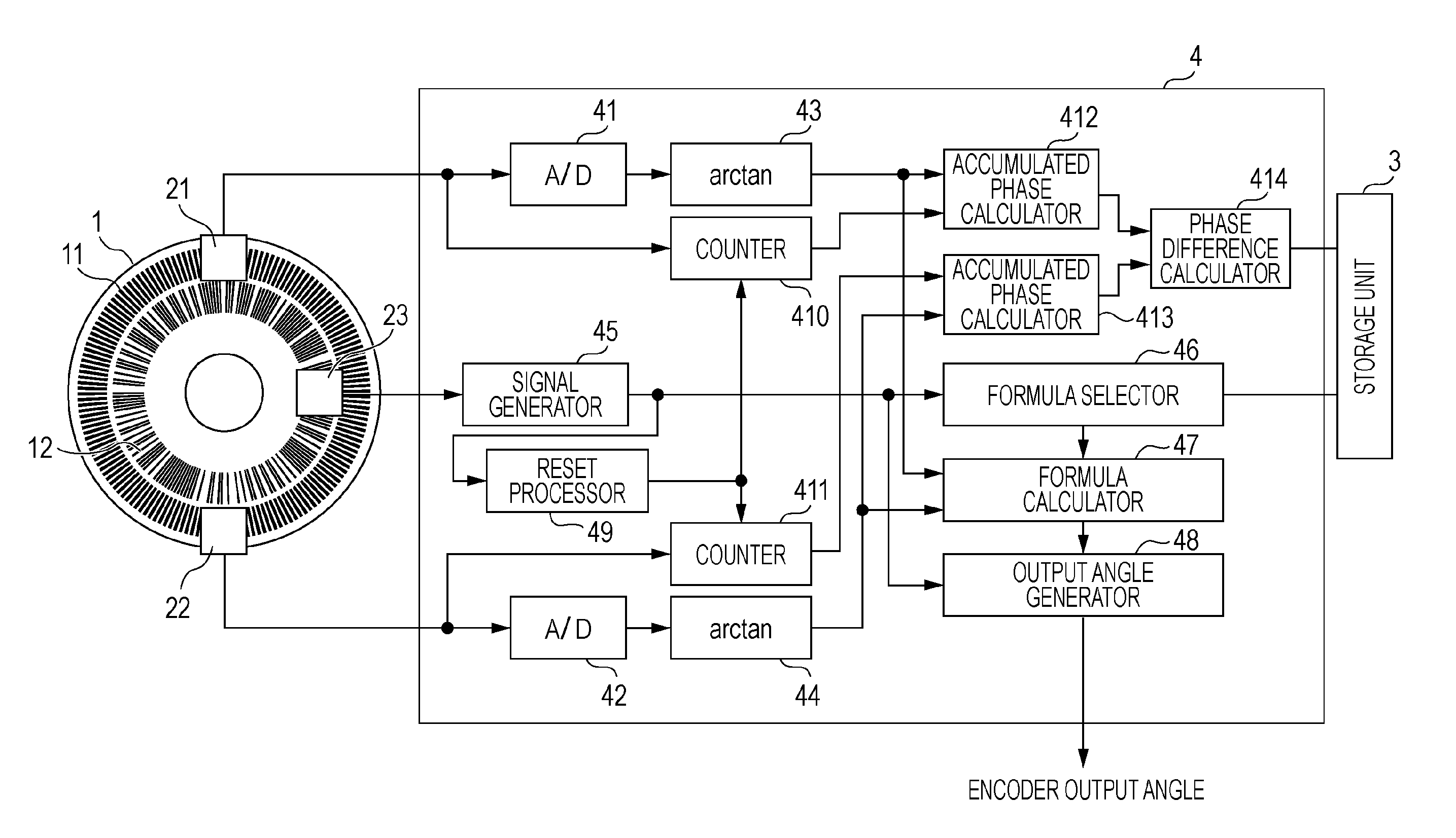
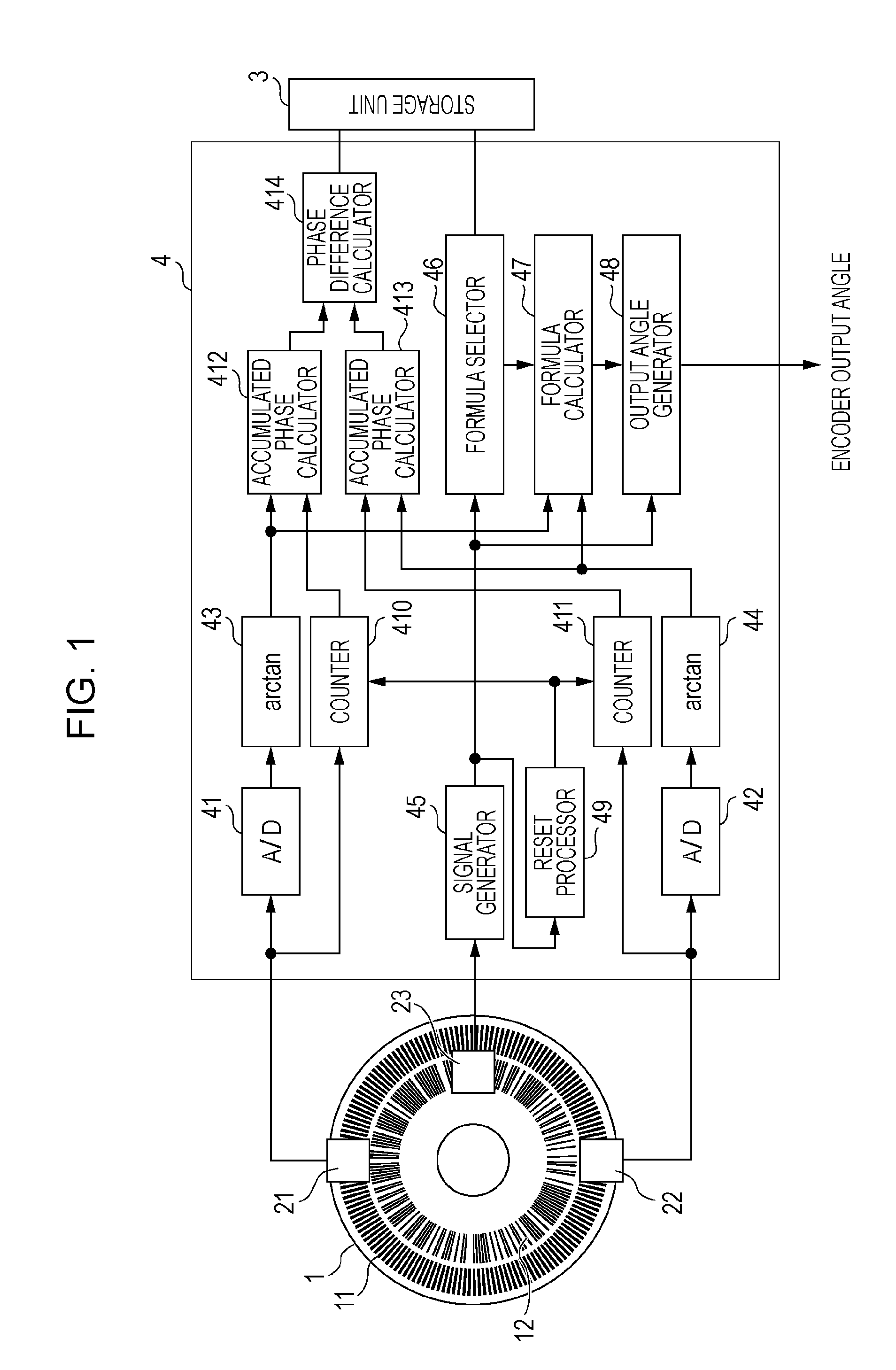
[0021]FIG. 1 is a block diagram of the rotary encoder according to the embodiment of the present invention. Referring to FIG. 1, the rotary encoder includes a scale 1, two first sensor units (first detection unit) 21 and 22, a second sensor unit (second detection unit) 23, a storage unit (storage unit) 3, and a controller 4.

[0022]A first track 11 and a second track 12 are formed on the scale 1. As the first track 11 rotates, incremental signals are output from the two first sensor units 21 and 22. As the second track 12 rotates, an absolute signal is output from the second sensor unit 23. The controller 4 performs an operation on the signals, which are output by the first and second sensor units 21, 22, and 23, by using a formula stored in the storage unit 3 to calcula...


PUM


Abstract

A rotary encoder includes two first detection units disposed at positions that are symmetrical about a rotation axis, each of the first detection units outputting an incremental signal, and second detection unit that outputs an absolute signal φA. The rotary encoder includes a storage unit that stores a plurality of formulas for correcting errors of the incremental signals, the formulas being different from each other in accordance with the signal φA, and the errors being generated due to eccentricity; a calculation unit that calculates a corrected phase φI by performing operation on the incremental signals by using one of the formulas corresponding to the signal φA; and a generation unit that generates a rotation angle of the scale on the basis of the phase φI and the signal φA.

Description

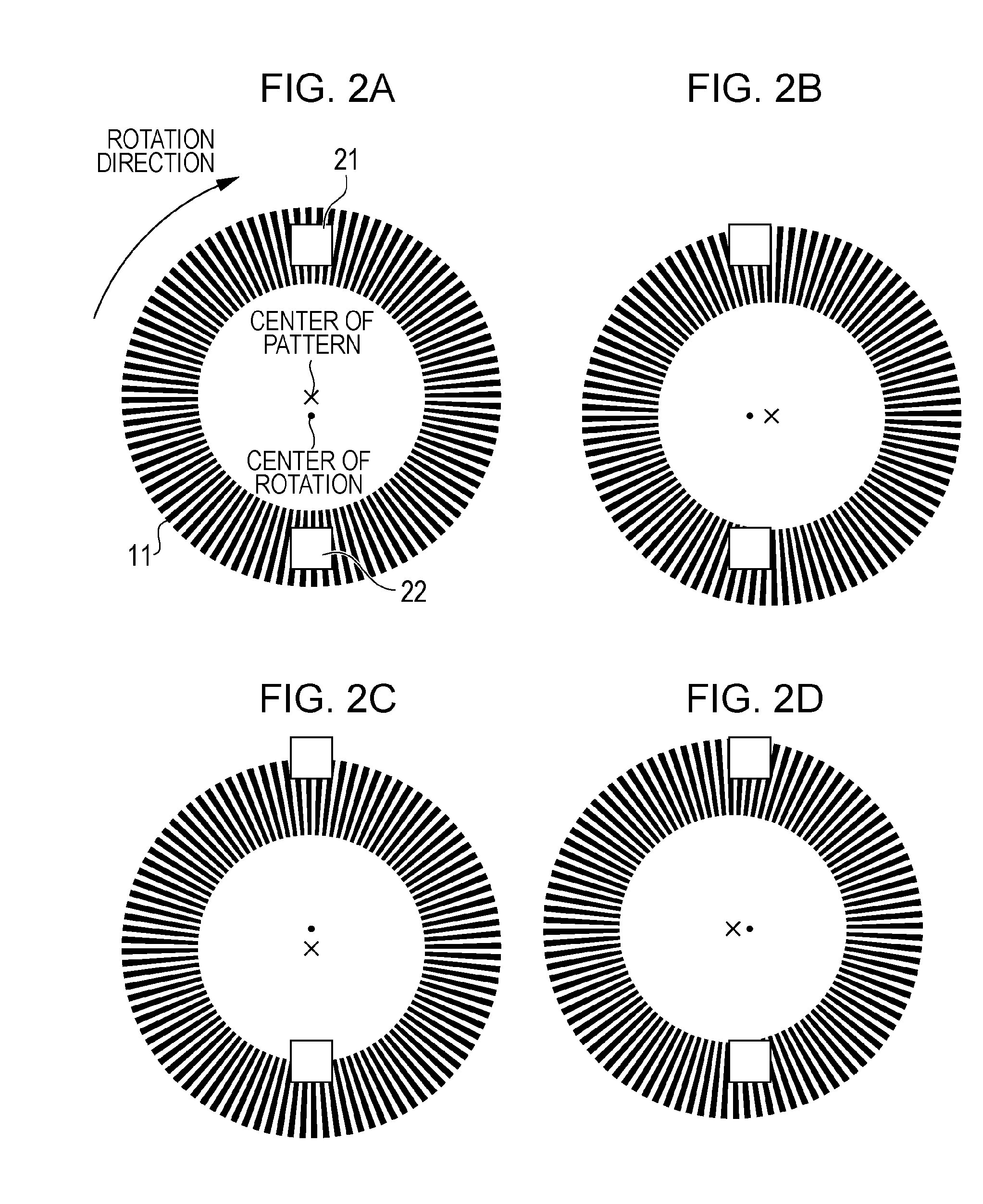
FIELD OF THE INVENTION[0001]The present invention relates to an absolute rotary encoder that detects a rotation angle on the basis of an absolute signal and an incremental signal, with higher precision than on the basis of only the absolute signal.DESCRIPTION OF THE RELATED ART[0002]Some existing rotary encoders include a sensor and a scale that rotates relative to the sensor, the scale having a pattern having a center that coincides with the center of rotation, and detect the rotation angle of the scale by detecting a change in the pattern by using the sensor.[0003]In such an encoder, if the center of the pattern is deviated from the center of rotation, the detected angle includes an eccentric error, which is a periodic error having a characteristic of a sinusoidal wave having a period for one rotation. Therefore, it is necessary to take measures against the eccentric error in order to detect the rotation angle with high precision. However, in reducing the deviation of the center o...

Claims


Application Information

Patent Timeline
IPC IPC(8): G01D5/34
CPCG01D5/2448
Inventor NAKAMURA, HITOSHI
Owner CANON KK
Learn More