

Method for cutting tempered glass plate
- Summary
- Abstract
- Description
- Claims
- Application Information
AI Technical Summary
Benefits of technology
Problems solved by technology
Method used
Image

Examples
embodiment 1
[0043]First, the structure of a strengthened glass sheet and a method for cutting the strengthened glass sheet will be described with reference to FIGS. 1 to 5.
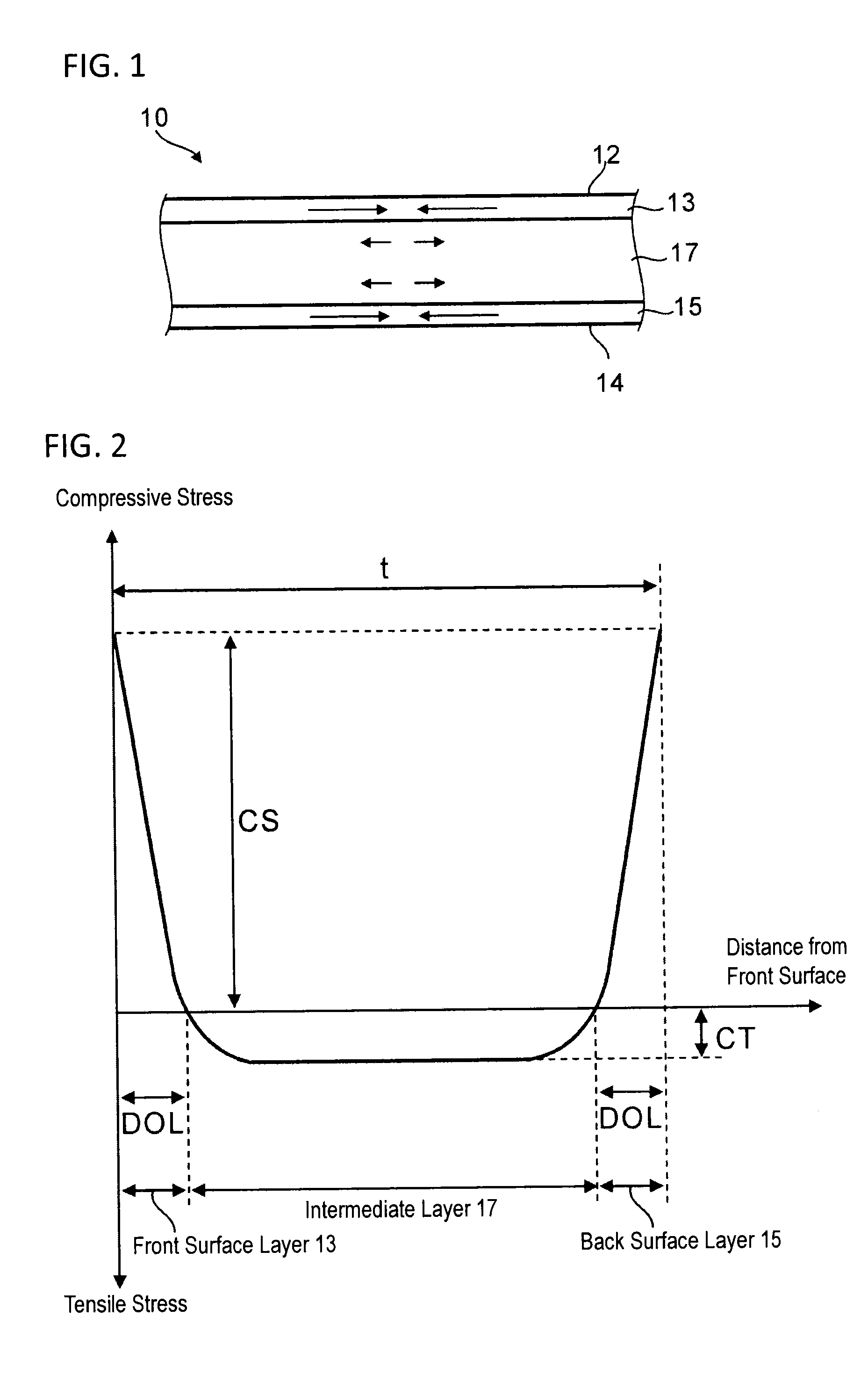
[0044]The structure of the strengthened glass sheet will be described with reference to FIGS. 1 and 2. FIG. 1 is a cross-sectional view of a strengthened glass sheet 10 before irradiation of laser light. In FIG. 1, the direction of an arrow indicates an acting direction of a residual stress, and the size of the arrow indicates the intensity of the stress. As illustrated in FIG. 1, the strengthened glass sheet 10 includes a front surface layer 13, a back surface layer 15, and an intermediate layer 17 provided between the front surface layer 13 and the back surface layer 15. In the front surface layer 13 and back surface layer 15, a compressive stress generated by the following air-quenching strengthening method or a chemical strengthening method remains. In addition, as a counteraction thereto, a tensile stress remains in the ...
example 1
[0133]In Example 1, for 21 samples (Samples 1 to 21) having different internal strain energies UCT, the relationships with the critical irradiation energy Ec were investigated. In Samples 18 to 21, non-strengthened glass sheets were used.
[0134]FIG. 14 is a view illustrating the shape of a cutting-scheduled line according to Example 1. As illustrated in FIG. 14, the cutting-scheduled line according to Example 1 includes two straight sections and two corner sections (curvature radius R=5 mm) constituting a crank shape.
[0135]For glass sheets for chemical strengthening, a glass raw material adjusted by mixing a plurality of kinds of raw materials was dissolved, and the dissolved molten glass was formed into a sheet shape. After the glass was slowly cooled to near room temperature, the glass was cut, machined, and mirror-polished on both surfaces, thereby producing 50 mm×50 mm glass sheets having a predetermined thickness. The glass raw materials were prepared by changing the amount of i...
example 2
[0178]In Example 2, the influence of the laser wavelength λ on the attachment of a foreign substance, which increased the absorptivity of the laser light, was investigated.
[0179]FIG. 17 is a table illustrating laser wavelengths λ, internal strain energies UCT, irradiation energies E, a variety of conditions for deriving both, the presence or absence of a black mark as a foreign substance, cutting possibilities, and cross-section properties in Samples 31 to 33 and 41 to 43. Specifically, from the left column of the table, the laser wavelength λ (nm), sample numbers, Young's moduli Y (MPa), the thicknesses t (μm) of the strengthened glass sheets, the surface compressive stress CS (MPa), the thicknesses DOL (μm) of the front surface layer and the back surface layer, the internal residual tensile stress CT (MPa), the internal strain energy UCT (J / m2), the scanning rate v (mm / s) of the laser light, the beam diameter φ (mm) of the laser light, the laser output P (W), the irradiation energ...
PUM
| Property | Measurement | Unit |
|---|---|---|
| Wavelength | aaaaa | aaaaa |
| Wavelength | aaaaa | aaaaa |
| Wavelength | aaaaa | aaaaa |
Abstract
Description
Claims
Application Information