Device, system, and method for transcatheter treatment of valvular regurgitation

a technology of valvular regurgitation and transcatheter, which is applied in the field of devices, systems and methods for transcatheter treatment of valvular regurgitation, can solve the problems of significant number of patients who may not take medications regularly, medication can suffer from lack of patient compliance, and pharmacological therapies of mitral valve regurgitation may be inconvenien

Active Publication Date: 2019-06-13
POLARES MEDICAL INC
View PDF0 Cites 61 Cited by
  • Summary
  • Abstract
  • Description
  • Claims
  • Application Information

AI Technical Summary

Benefits of technology

[0022]In some embodiments, an advantage is the ability to expand the coaptation assistance element. In some embodiments, one or more purse-string sutures, or portions thereof, are released to expand the coaptation assistance element. In some embodiments, release of the purse-string suture allows one or more struts to assume a neutral configuration. In some embodiments, the release of the purse-string suture allows one or more struts to assume a pre-shaped curve. In some embodiments, the one or more struts comprise NiTi. In some embodiments, the purse-string suture can be repeatedly tensioned and / or released. In some embodiments, the purse-string suture is captive within the coaptation assistance element. In some embodiments, the purse-string suture is tensioned to remove the coaptation assistance element from a patient. In some embodiments, the purse-string suture is released to deploy the coaptation assistance element within the heart of a patient. In some embodiments, the purse-string suture can be selective deployed to expand a portion of coaptation assistance element while another portion of the coaptation assistance element remains collapsed or partially collapsed.
[0023]In some embodiments, an advantage is the ability to adjust the coaptation assistance element. In some embodiments, the coaptation assistance element can be held by a central location. In some embodiments, the central location is the anchor. In some embodiments, the central location is the hub. In some embodiments, the hub and / or the anchor are located generally near a mid-point of the diameter of the coaptation assistance element. In some embodiments, the hub and / or the anchor are generally located near a mid-point and / or central location of the annular portion of the coaptation assistance element. In some embodiments, the coaptation assistance element can be held at a neutral position. In some embodiments, the coaptation assistance element can be rotated by rotating a delivery catheter connected to the annular hub. In some embodiments, the coaptation assistance element can be moved longitudinally by corresponding longitudinal motion of a delivery catheter connected to the annular hub.
[0024]In some embodiments, an advantage is the coaptation assistance element can be retained by a delivery catheter after the coaptation assistance element is positioned. In some embodiments, the coaptation assistance element can be fully deployed within the mitral valve but still tethered to a delivery catheter. In some embodiments, the coaptation assistance element can be adjusted after the coaptation assistance element is fully deployed within the mitral valve. In some embodiments, the coaptation assistance element can be rotated about the hub after the coaptation assistance element is fully deployed. In some embodiments, the anchor can be disengaged and / or reengaged with the tissue after the coaptation assistance element is fully deployed. In some embodiments, the purse-string sutures can collapse and / or expand the coaptation assistance element or a portion thereof after the coaptation assistance element is fully deployed. In some embodiments, the coaptation assistance element can be recaptured after the coaptation assistance element is fully deployed. In some embodiments, the coaptation assistance element can be removed after the coaptation assistance element is fully deployed.
[0025]In some embodiments, an advantage is the coaptation assistance element does not require ventricular attachment. In some embodiments, the coaptation assistance element only requires annular attachment. In some embodiments, the coaptation assistance element only requires attachment of an annular anchor through an annular hub. In some embodiments, the coaptation assistance element only requires attachment of an annular anchor through an annular hub and annular barbs. In some embodiments, the coaptation assistance element only requires attachment of an annular anchor through an annular hub, annular barbs, and / or commissural barbs.
[0026]In some embodiments, an advantage is the radially extending frame. In some embodiments, the frame comprises an annular hub and one or more struts. In some embodiments, the struts extend radially from the annular hub. In some embodiments, the frame is constructed from a single, planar sheet of material. In some embodiments, the frame is precisely cut using water jet, laser etching or similar technology. In some embodiments, the frame is constructed by forming the annular hub with an edge of the frame. In some embodiments, the planar sheet of material is formed into a loop which becomes the annular hub. In some embodiments, the struts are bent to the desired configuration. In some embodiments, the struts are equally spaced about the circumference of the annular hub. In some embodiments, the struts are unequally spaced about the circumference of the annular hub. In some embodiments, the struts extending along a portion of the circumference of the annular hub are different than struts extending along another portion of the circumference of the annular hub. In some embodiments, one or more designated portions of the struts are designed to be placed near the annular region of the heart. In some embodiments, one or more designated portions of the struts are designed to be placed near the commissure region of the heart. In some embodiments, one or more designated portions of the struts are designed to be placed near the ventricular region of the heart. In some embodiments, the struts of the radially outward frame do not intersect. In some embodiments, the struts of the radially outward frame do not form a mesh. In some embodiments, the struts of the radially outward frame extend in a line from the hub to an edge of the coaptation assistance element. In some embodiments, the struts of the radially outward frame have a sharpened edge. In some embodiments, the sharpened edge extends in a straight line from the edge of the coaptation assistance element. In some embodiments, the sharpened edge is integrally formed in the strut. In some embodiments, a strut of the radially outward frame has one or more radii of curvature. In some embodiments, a strut of the radially outward frame can be concave or convex or both concave and convex along the length of the strut. In some embodiments, a strut of the radially outward frame has one or more inflection points.
[0027]In some embodiments, an advantage is the curvature of the frame. In some embodiments, the annular hub is radially extending. In some embodiments, the annular hub extends from the coaptation assistance element away from the annulus. In some embodiments, the annular hub extends from a surface of the coaptation assistance element above a planar surface of the struts. In some embodiments, an edge of the coaptation assistance element is curved. In some embodiments, one or more struts may curve laterally from the annular hub toward the superior edge. In some embodiments, the superior edge of the coaptation assistance element can curve upward from the annulus. In some embodiments, the superior edge of the coaptation assistance element can curve upward from the posterior leaflet. In some embodiments, the superior edge of the coaptation assistance element can curve downward toward the annulus. In some embodiments, the superior edge of the coaptation assistance element can curve downward toward the posterior leaflet. In some embodiments, one or more struts may curve laterally from the annular hub toward the inferior edge. In some embodiments, the inferior edge of the coaptation assistance element can curve away from the posterior leaflet. In some embodiments, the inferior edge of the coaptation assistance element can curve toward the posterior leaflet.

Problems solved by technology

A variety of therapies have been applied for treatment of mitral valve regurgitation, and still other therapies may have been proposed but not yet actually used to treat patients.
However, medications can suffer from lack of patient compliance.
A significant number of patients may occasionally (or even regularly) fail to take medications, despite the potential seriousness of chronic and / or progressively deteriorating mitral valve regurgitation.
Pharmacological therapies of mitral valve regurgitation may also be inconvenient, are often ineffective (especially as the condition worsens), and can be associated with significant side effects (such as low blood pressure).
Regardless, open mitral valve surgery is generally a very invasive treatment carried out with the patient under general anesthesia while on a heart-lung machine and with the chest cut open.
Complications can be common, and in light of the morbidity (and potentially mortality) of open-heart surgery, the timing becomes a challenge—sicker patients may be in greater need of the surgery, but less able to withstand the surgery.
Procedures that are done with robots or through endoscopes are often still quite invasive, and can also be time consuming, expensive, and in at least some cases, quite dependent on the operator's skill.
While these various approaches and tools have met with differing levels of acceptance, none has yet gained widespread recognition as an ideal therapy for most or all patients suffering from mitral valve regurgitation.
Unfortunately, sealing between the native leaflets and the full perimeter of a balloon or other coaxial body may prove challenging, while the significant contraction around the native valve annulus during each heart beat may result in significant fatigue failure issues during long-term implantation if a buttress or anchor interconnecting cross member is allowed to flex.
Moreover, the significant movement of the tissues of the valve may make accurate positioning of the implant challenging regardless of whether the implant is rigid or flexible.

Method used


Image

  • Device, system, and method for transcatheter treatment of valvular regurgitation
  • Device, system, and method for transcatheter treatment of valvular regurgitation
  • Device, system, and method for transcatheter treatment of valvular regurgitation

Examples


Embodiment Construction

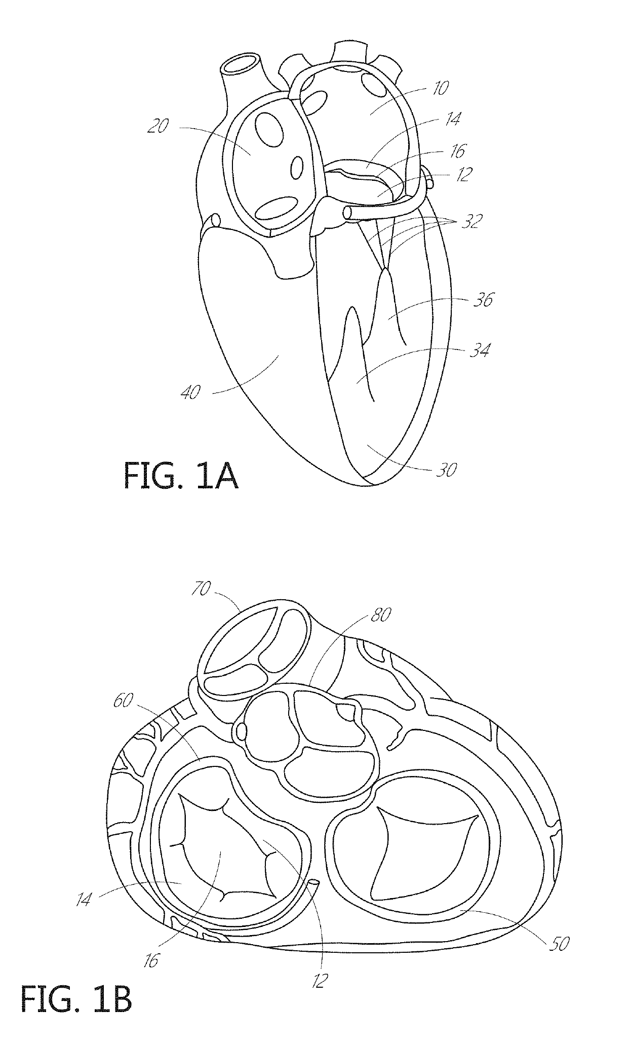
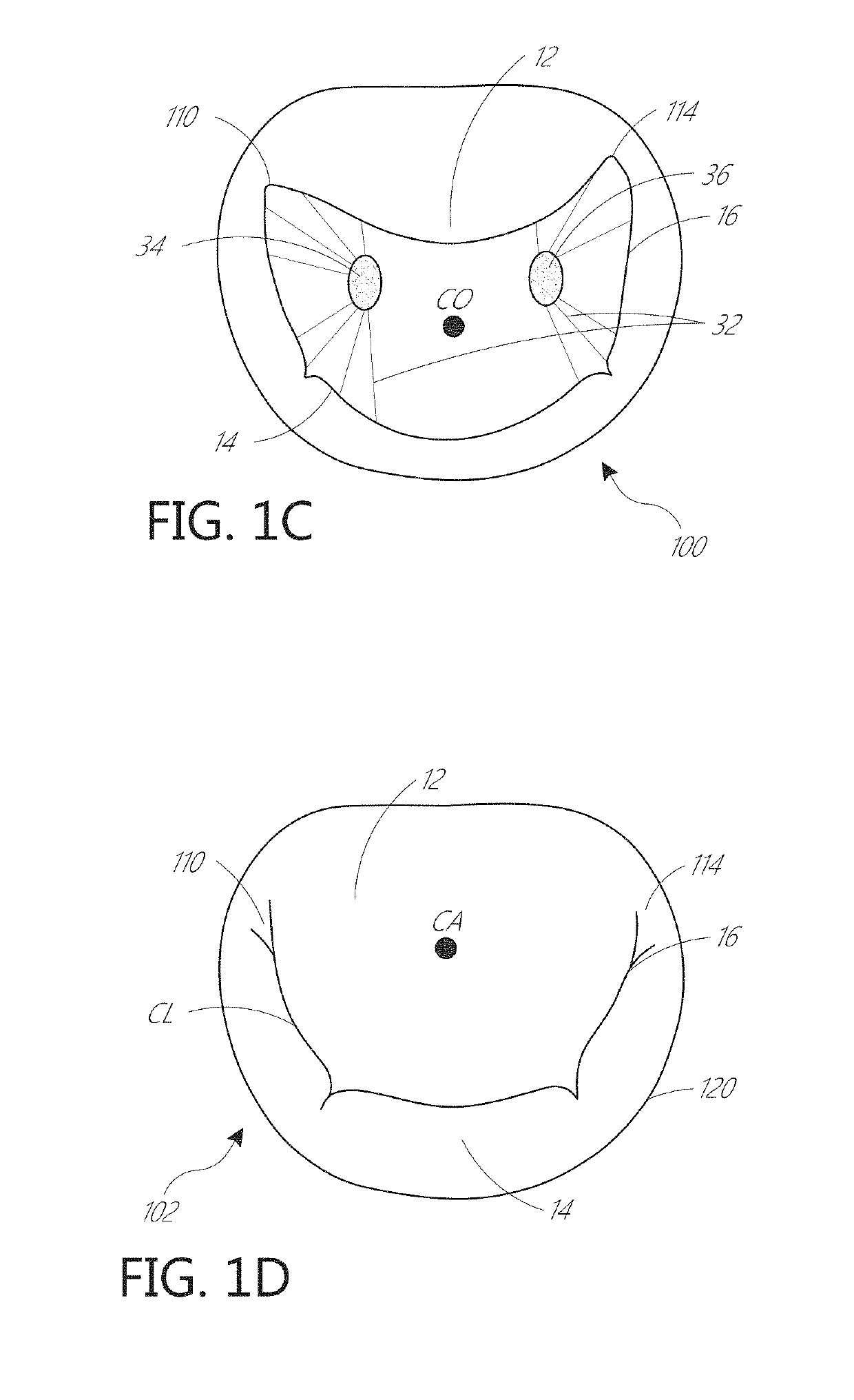
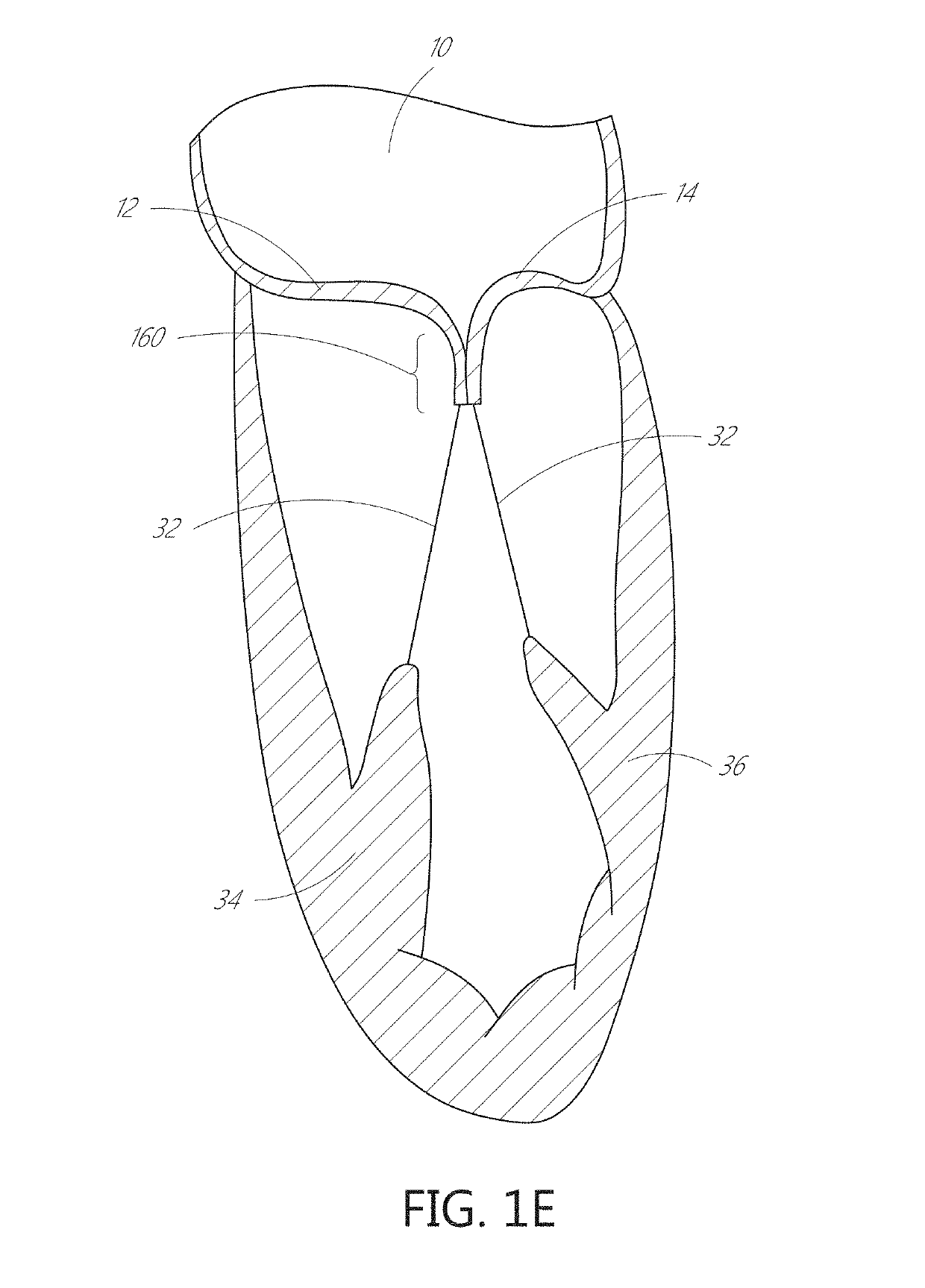
[0128]The present invention, in some embodiments, generally provides improved medical devices, systems, and methods, often for treatment of mitral valve regurgitation and other valve diseases including tricuspid regurgitation. While the description that follows includes reference to the anterior leaflet in a valve with two leaflets such as the mitral valve, it is understood that “anterior leaflet” could refer to one or more leaflets in valve with multiple leaflets. For example, the tricuspid valve has 3 leaflets so the “anterior” could refer to one or two of the medial, lateral, and posterior leaflets. The coaptation assistance elements described herein will generally include a coaptation assist body (sometimes referred to herein as a valve body) which is generally along the blood flow path as the leaflets of the valve move back and forth between an open-valve configuration (with the anterior leaflet separated from valve body) and a closed-valve configuration (with the anterior leaf...


PUM


Abstract

The invention relates to a device for use in the transcatheter treatment of mitral valve regurgitation, specifically a coaptation assistance element for implantation across the valve; a system including the coaptation assistance element and anchors for implantation; a system including the coaptation assistance element and delivery catheter; and a method for transcatheter implantation of a coaptation element across a heart valve.

Description

CROSS-REFERENCE TO RELATED APPLICATIONS[0001]The present application is a continuation-in-part application of U.S. application Ser. No. 16 / 129,194 filed Sep. 12, 2018, which is a continuation-in-part application of U.S. application Ser. No. 15 / 918,988 filed Mar. 12, 2018, which claims priority under 35 U.S.C. § 119(e) to U.S. Provisional Application No. 62 / 470,684, filed on Mar. 13, 2017. Each of the foregoing applications of which are hereby incorporated by reference in their entireties. Any and all applications for which a foreign or domestic priority claim is identified in the Application Data Sheet as filed with the present application, are hereby incorporated by reference in their entirety under 37 CFR 1.57.BACKGROUNDField[0002]The present disclosure generally provides improved medical devices, systems, and methods, typically for treatment of heart valve disease and / or for altering characteristics of one or more valves of the body. Embodiments include implants for treatment of ...

Claims


Application Information

Patent Timeline
Patent Type & Authority Applications(United States)
IPC IPC(8): A61F2/24
CPCA61F2/2457A61F2220/0016A61F2/2463A61F2/2409A61F2230/0091A61F2/2466A61F2/2445A61F2/2412A61B17/068A61B2017/00243A61B2017/00358A61B2017/00477A61B2017/0649A61B2090/3966A61F2/2454A61B2017/00871A61B2017/00867A61B2090/378A61B2090/376
Inventor KHAIRKHAHAN, ALEXANDER K.
Owner POLARES MEDICAL INC
Why Eureka
Try Eureka