Handheld device having lateral illumination for keypad

Inactive Publication Date: 2011-06-23
AMTRAN TECH
10 Cites 5 Cited by

AI-Extracted Technical Summary

Problems solved by technology

But in the environment lacking enough ambient light, when watching movies for example, it is quite inconvenient to operate these buttons of a...

Method used

[0018]Please refer to FIG. 2. FIG. 2 is a schematic diagram showing functions performed at a side of the handheld device 1 in an embodiment. As FIG. 1 and FIG. 2 show, after the second body 20 and the first body 10 slide away with respect to each other to be opened, the lighting element 24 at the side, which faces the first keypad 11 of the first body 10, of the housing 21 of the second body 20 projects light toward the surface of the first keypad 11 to illuminate the first keypad 11 in a dark environment. In this embodiment, the lighting element 24 is composed of a plurality of light emitting diode (LED) chips 241, which locate at the side of the housing 21 of the second body 20 and align in a row along a direction parallel with the surface of the first keypad 11, wherein the side of the housing 21 faces a side of the first body 10. The plurality of LED chips 241 is illustratively aligned along direction L1L2 parallel with the long side of the first keypad 11 as shown in FIG. 1. In such way, each area of the first keypad 11 can be homogeneously and thoroughly covered by light emitted from the lighting element 24. Light emitted by each LED chip 241 is mainly projected toward the surfaces of different areas of the first keypad 11 in a manner that the projection dircection is substantially parallel with the surface of the first keypad 11. The first keypad 11 can be illuminated with sufficient light strength so that a user can clearly see buttons on the keypad 11. As a result, the lighting element 24 can effectively illuminate the keypad 11 with relatively small emitting power under such configuration. Moreover, electric power is also saved.
[0021]Additionally, the handheld device 1 may further include a light sensor that is used to adjust the light strength of the lighting element 24 under various ambient brightness for adaptive illumination and saving power. As shown in FIG. 2, the light sensor 28 outputs corresponding sensing voltage according to the ambient brightness, and the control unit 27 then controls the lighting element 24 to emit light with corresponding strength according to the outputted sensing voltage from the light sensor 28.
[0022]Please refer to FIG. 3. FIG. 3 is a schematic diagram showing that the handheld device 1 changes lighting strength of the lighting element 24 according to the ambient brightness. In the embodiment of the invention, two threshold values, a first threshold value and a second threshold value for example, may be set in connection with the sensing voltage about the ambient brightness. When the environment is relativ...

Benefits of technology

[0008]The invention uses a low cost and indicating lighting element on the extensively used slider type handheld devices. When a top cover and a bottom cover of the handheld device slide away with respect to each other, the lighting element at the side of the top cover laterally illuminates a keypad on the bottom cover,...

Abstract

A handheld device includes a row of lighting elements configured at the side of its top body that faces a keypad of its bottom body for illuminating the keypad when the two bodies slide away for use. The lighting elements projects light in a direction nearly parallel with the keypad and toward the surface of the keypad, and illumination of the keypad is therefore accomplishable in various environmental conditions. The lighting elements may also be used for illuminating the keypad or displayed with different strength or bright and dark periods based on the ambient brightness, and based on the charging rate of the handheld device's rechargeable battery when the handheld device is being charged.

Application Domain

Batteries circuit arrangementsEmergency casings +10

Technology Topic

Charge rateGlobal illumination +6

Image

  • Handheld device having lateral illumination for keypad
  • Handheld device having lateral illumination for keypad
  • Handheld device having lateral illumination for keypad

Examples

  • Experimental program(1)

Example

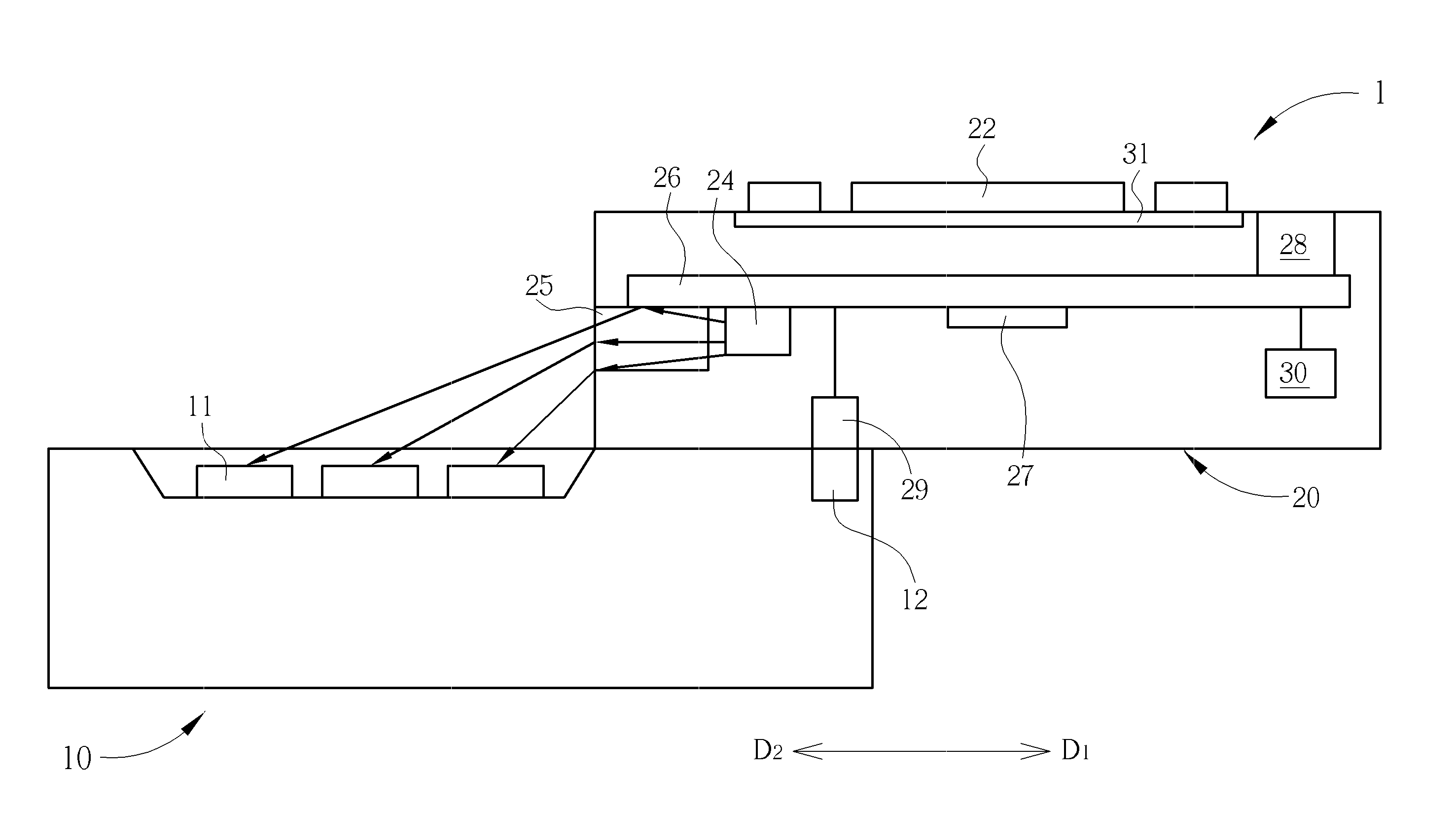
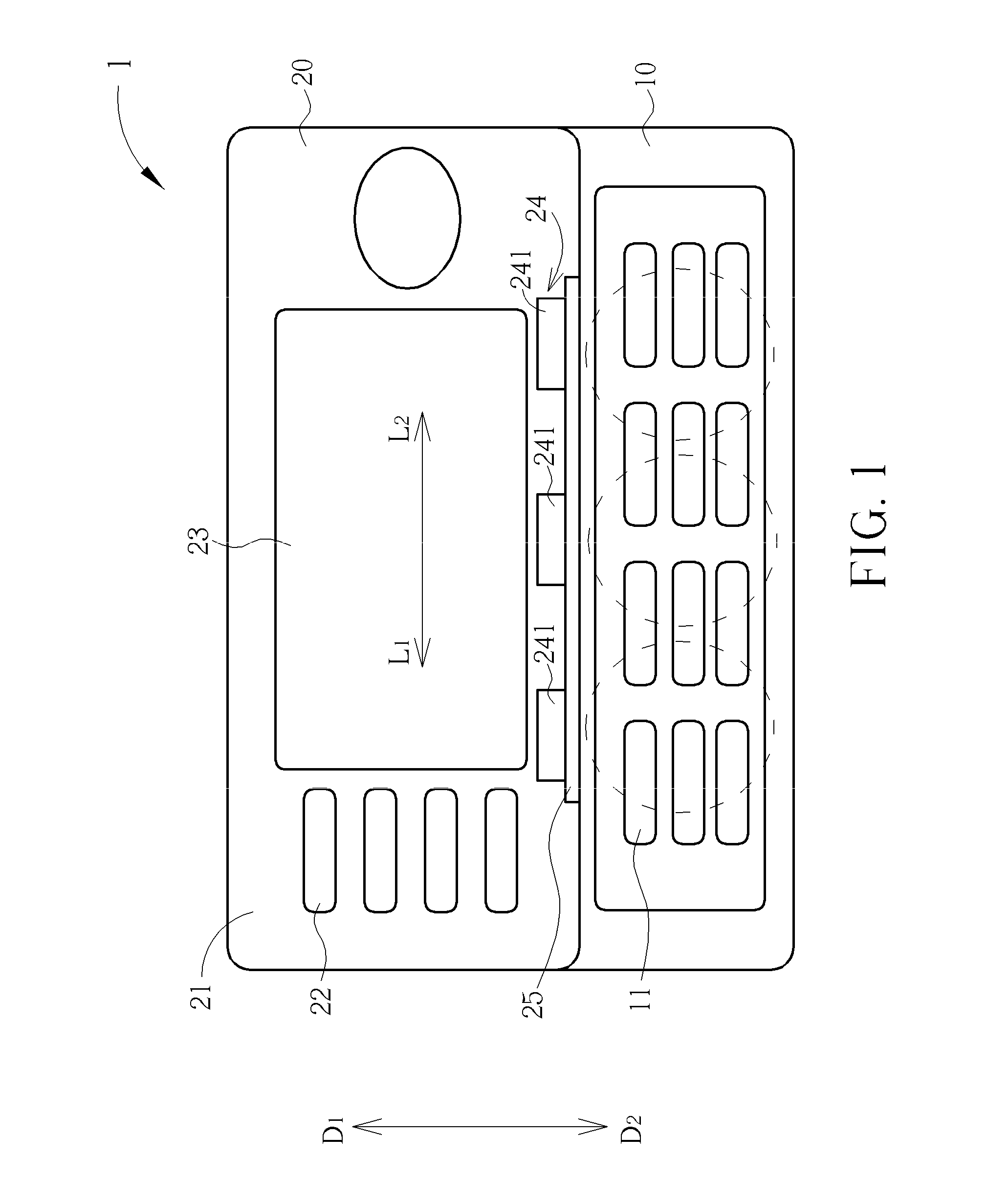
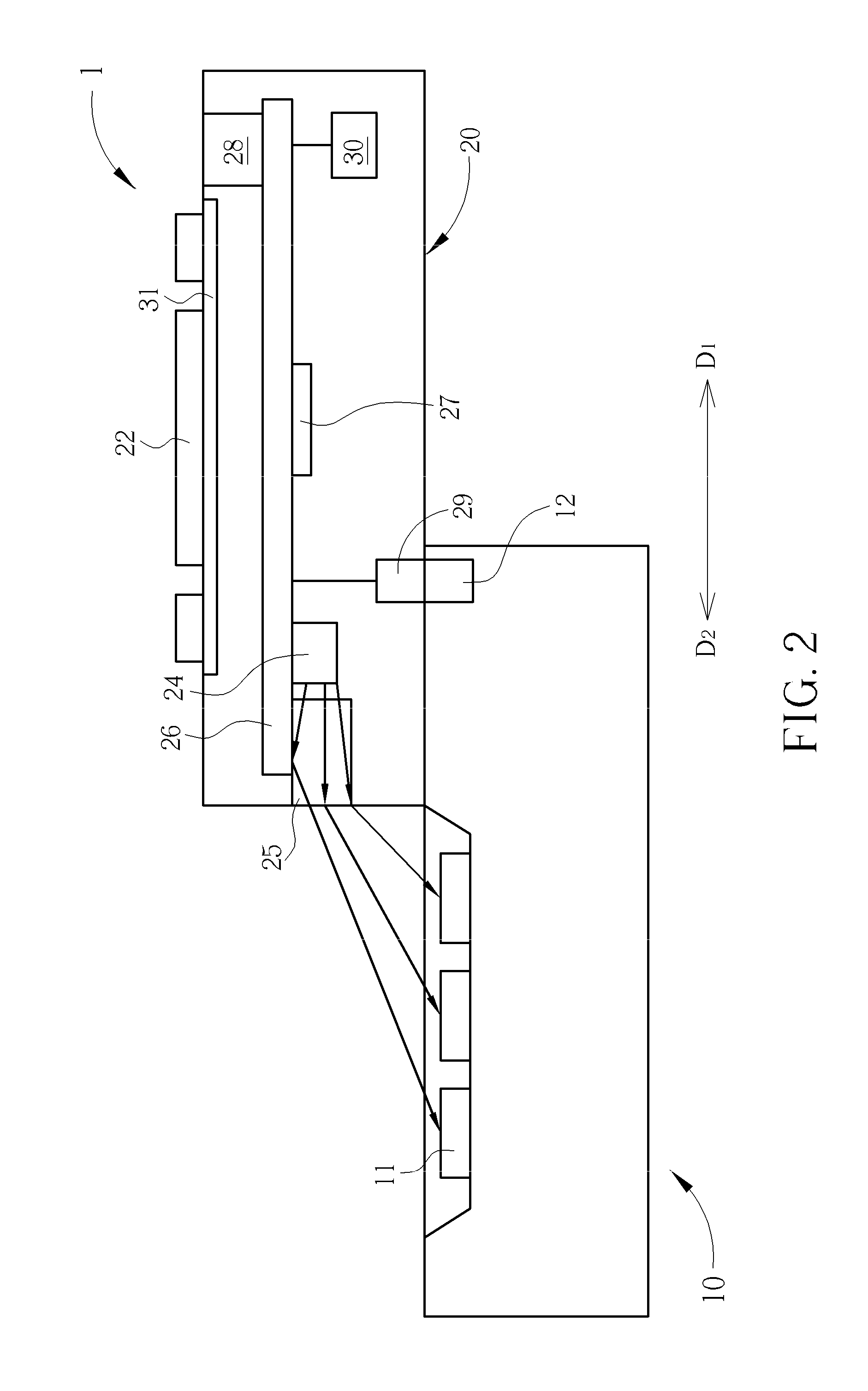
[0016]Please refer to FIG. 1. FIG. 1 is a schematic diagram of an embodiment of a handheld device 1 disclosed in the invention. The handheld device 1 is preferably a slider type remote controller that includes a first body 10 and a second body 20 capable of sliding with respect to each other. The first body 10 is in parallel slidable along direction D1D2 relative to the second body 20, to be closed or to be opened. When the first body 10 slides along direction Di relative to the second body 20 to be closed, the handheld device 1 has relatively small size and can be operated through the second body 20. When the first body 10 slides along direction D2 relative to the second body 20 to be opened, the first body 10 is exposed for full operation.
[0017]The first body 10 includes a first keypad 11, which has a plurality of buttons for complicated control, and the second body 20 includes a second keypad 22 and a display panel 23. Considering utility setup and convenience, the display panel 23 may be a touch panel or a common one, or directly removed from the handheld device 1, while the second keypad 22 may include opaque buttons that do not emit light, or use backlight illumination, such as a backlight element 31 in FIG. 2. The second keypad 22 may also use light-transmissible buttons such that the second keypad 22 may also be illuminated for smooth operation. Since either the first keypad 11 or the second keypad 22 needs proper illumination for easy operation such that the handheld device 1 can be operated in dark environment, the first keypad 11, in the embodiment of the invention, is further provided with illumination by a lighting element 24 disposed at a side of a housing 21 of the second body 20.
[0018]Please refer to FIG. 2. FIG. 2 is a schematic diagram showing functions performed at a side of the handheld device 1 in an embodiment. As FIG. 1 and FIG. 2 show, after the second body 20 and the first body 10 slide away with respect to each other to be opened, the lighting element 24 at the side, which faces the first keypad 11 of the first body 10, of the housing 21 of the second body 20 projects light toward the surface of the first keypad 11 to illuminate the first keypad 11 in a dark environment. In this embodiment, the lighting element 24 is composed of a plurality of light emitting diode (LED) chips 241, which locate at the side of the housing 21 of the second body 20 and align in a row along a direction parallel with the surface of the first keypad 11, wherein the side of the housing 21 faces a side of the first body 10. The plurality of LED chips 241 is illustratively aligned along direction L1L2 parallel with the long side of the first keypad 11 as shown in FIG. 1. In such way, each area of the first keypad 11 can be homogeneously and thoroughly covered by light emitted from the lighting element 24. Light emitted by each LED chip 241 is mainly projected toward the surfaces of different areas of the first keypad 11 in a manner that the projection dircection is substantially parallel with the surface of the first keypad 11. The first keypad 11 can be illuminated with sufficient light strength so that a user can clearly see buttons on the keypad 11. As a result, the lighting element 24 can effectively illuminate the keypad 11 with relatively small emitting power under such configuration. Moreover, electric power is also saved.
[0019]For example, an LED chip 241 has different emitting strength as different electric current is supplied to the LED chip 241. In a preferred embodiment of the invention, each LED chip 241 of the lighting element can receive 4-15 mA current, and 3-4 LED chips 241 are configured at one side of the housing 21 for thoroughly and uniformly illuminating the whole first keypad 11. Additionally, a diffuser 25 can further be configured between the side of the second body 20 (the side neighboring the first keypad 11) and the lighting element 24 such that light from the lighting element 24 may go through the diffuser 25 first before reaching the first keypad 11. Light emitted from each LED chip 241 is homogenized by the diffuser 25 and then projected toward the surface of the first keypad 11. Each LED chip 241 is a point light souce, but is effectively transferred as a surface source or a line source by the diffuser 25 so that illumination on the first keypad 11 is more uniform.
[0020]FIG. 2 shows that the lighting element 24 is controlled to emit light by a control unit 27 configured in the second body 20. Both the control unit 27 and the lighting element 24 are configured at a circuit board 26 in the second body 20. The second body 20 may further include a light sensor 28, a second triggering component 29 and a battery module 30, all of which being electrically connected to one another and configured at the circuit board 26. The first body 10 further includes a first triggering component 12 that is utilized to trigger the second triggering component 29, by either electromagnetically sensing or mechanically switching, when the first body 10 slides along direction D2 relative to the second body 20 to an opened position as shown in FIG. 1 or FIG. 2. The control unit 27 then controls the lighting element 24 to illuminate the surface of the first keypad 11. As the first body 10 and the second body 20 are closed with respect to each other, the two triggering components 12, 29 are inactive and the lighting element 24 is turned off.
[0021]Additionally, the handheld device 1 may further include a light sensor that is used to adjust the light strength of the lighting element 24 under various ambient brightness for adaptive illumination and saving power. As shown in FIG. 2, the light sensor 28 outputs corresponding sensing voltage according to the ambient brightness, and the control unit 27 then controls the lighting element 24 to emit light with corresponding strength according to the outputted sensing voltage from the light sensor 28.
[0022]Please refer to FIG. 3. FIG. 3 is a schematic diagram showing that the handheld device 1 changes lighting strength of the lighting element 24 according to the ambient brightness. In the embodiment of the invention, two threshold values, a first threshold value and a second threshold value for example, may be set in connection with the sensing voltage about the ambient brightness. When the environment is relatively bright, the sensing voltage generated by the light sensor 28 that senses the ambient brightness would be greater than the first threshold value, as illustrated in part A of FIG. 3. With a bright environment, the handheld device 1 can be configured not to activate the keypad illumination function when the handheld device 1 is sliding opened, i.e., the control unit 27 controls the lighting element 24 not to emit light to prevent unnecessary power consumption. As the environment is relatively dark, the sensing voltage generated by the light sensor 28 that senses the ambient brightness would be smaller than the second threshold value, as illustrated in part C of FIG. 3. Now the first keypad 11 needs enough illumination for operation in such dark environment and the control unit 27 is configured to supply maximum current for the lighting element 24 (for example, each LED chip 241 can preferably receive 10-15 mA) to illuminate the first keypad 11 with the maximum strength.
[0023]When the ambient brightness is between the aforementioned two conditions, the light sensor 28 detects the ambient brightness and outputs a sensing voltage falling between the first threshold value and the second threshold value, as illustrated in part B of FIG. 3. At such situation, the handheld device 1 provides illumination for the first keypad 11 with a suitable extent according to the ambient brightness, where the strength of illumination is in inverse proportion to the ambient brightness so as to provide the user relatively comfortable operation experience. That is, as the ambient brightness gets brighter, the sensing voltage generated by the light sensor 28 is higher, and the control unit 27 controls the lighting element 24 to emit light with a relatively low strength according to the sensing voltage. On the contrary, as the ambient brightness gets darker, the sensing voltage generated by the light sensor 28 is lower, and the control unit 27 controls the lighting element 24 to emit light with a relative high strength according to the sensing voltage. By controlling the illuminating strength according to the ambient brightness, the handheld device 1 also reduces the power consumption and prolongs the life of its battery module. Additionally, FIG. 3 shows that the activation of the lateral illumination for the first keypad 11 may also be delayed once the first body 10 slides relative to the second body 20 to the opened position. The lighting element 24 is controlled to emit light after delaying a predetermined time t so that the invention can have more variety in application.
[0024]Besides the way as shown in FIG. 3 that the first keypad 11 is illuminated by steady strength according to the ambient brightness, in other embodiments of the invention, the lighting element 24 may also be controlled to illuminate the first keypad 11 in a slowly transition period (from the bright status to the dark status) according to the ambient brightness. FIG. 4 illustrates a schematic diagram showing that the handheld device 1 changes the frequency at which the lighting element 24 changes illumination between the bright and dark statuses according to the ambient brightness. Once the control unit 27 receives the sensing voltage X generated by the light sensor 28 detecting the ambient brightness, it controls the lighting element 24 by using pulse width modulation (PWM) method such that the lighting element 24 emits light in a period T1 and changes its lighting strength between the maximum strength and the minimum strength. In a preferred embodiment the period T1 can be deduced by the following equation:
T1=1/(M−X);
[0025]where M is an input voltage required by the lighting element 24 to emit light with maximum strength or a specified voltage provided for the lighting element 24, and X is a sensing voltage generated by the light sensor 28 detecting the ambient brightness. As mentioned earlier, the sensing voltage X is in proportion with the ambient brightness and is set not to be greater than the specified voltage M of the lighting element 24. For example, if the specified voltage M of the lighting element 24 is 4.2 Volt, and as the light sensor 28 detects the ambient brightness and generates the sensing voltage X to be 3 Volt (meaning a darker environment), the period T1 would be 0.8 second, which implies a faster alteration between brightness and darkness; as the light sensor 28 detects the ambient brightness and generates the sensing voltage X to be 4 Volt (meaning a brighter environment), the period T1 would be 5 second, which implies a much slower alteration between brightness and darkness.
[0026]By use of such control method, when in brighter environment, the lighting element 24 of the handheld device 1 changes the strength between the brightest and the darkest statuses at a relatively slow pace, while in darker environment, the lighting element 24 changes the strength between the brightest and the darkest statuses at a relatively fast pace. The handheld device 1 can have various illumination effects according to the ambient brightness, and the time delay effect (t) as mentioned before and illustrated in FIG. 4 can also be implemented herein.
[0027]Please refer to FIG. 5. FIG. 5 illustrates a schematic diagram showing that the handheld device 1 changes the frequency at which the lighting element 24 changes illumination between the bright and dark statuses according to the charging rate. In addition to the function that the handheld device 1 controls the lighting element 24 to illuminate the first keypad 11 with a variety of effects when the first body 10 and the second body 20 are sliding to be opened, the lighting element 24 may further be used for other extensive applications. For example, the battery module 30 in FIG. 2, which is not limited to be configured at the second body 20, may be a rechargeable battery module that provides power for the handheld device 1. As the battery module 30 is being charged, whenever the handheld device 1 is set in a closed position or in the opened position, the lighting element 24 may further be controlled by the control unit 27 and utilized for displaying the charging rate of the battery module 30. In FIG. 5 for example, the battery module 30 has specified voltage N when its capacity is full. The battery module 30 also has a charging voltage V when it is being charged and the charging voltage V varies with the charging time. The control unit 27 controls the lighting element 24 by pulse width modulation (PWM) method as the battery module 30 is being charged such that the lighting element 24 emits light in a period T2 and changes its lighting strength between its maximum strength and minimum strength to display the charging status of the battery module 30. In a preferred embodiment, the period T2 can be deduced by the following equation:
T2=1/(N−V);
[0028]where the charging voltage V increases with the percentage of completion of charging and reaches to the specified voltage N. As a result, when the charging voltage V of the battery module 30 is at a low level, which represents an initial charging stage or low percentage of charging completion, the lighting element 24 of the handheld device 1 is controlled to alternate between the brightest and the darkest statuses in a relatively fast pace; when the charging voltage V of the battery module 30 is at a high level, which represents a final charging stage or high percentage of charging completion, the lighting element 24 is then controlled to alternate between the brightest and the darkest statuses in a relatively slow pace. The lateral illumination of the handheld device 1 therefore provides effective indication of charging completeness.
[0029]The embodiments of the invention disclose a handheld device including a row of lighting elements configured at the side of its top body that faces a keypad of its bottom body for illuminating the keypad when the two bodies slide away for use. The lighting elements projects light in a direction nearly parallel with the keypad and toward the surface of the keypad, and illumination of the keypad is therefore accomplishable in various environmental conditions. The lighting elements may also be used for illuminating the keypad or displayed with different strength or bright and dark periods based on the ambient brightness, and based on the charging rate of the handheld device's rechargeable battery when the handheld device is being charged.
[0030]Those skilled in the art will readily observe that numerous modifications and alterations of the device and method may be made while retaining the teachings of the invention.

PUM

no PUM

Description & Claims & Application Information

We can also present the details of the Description, Claims and Application information to help users get a comprehensive understanding of the technical details of the patent, such as background art, summary of invention, brief description of drawings, description of embodiments, and other original content. On the other hand, users can also determine the specific scope of protection of the technology through the list of claims; as well as understand the changes in the life cycle of the technology with the presentation of the patent timeline. Login to view more.

Similar technology patents

Apparatus and method for low-density cellular wood plastic composites

InactiveUS20050067729A1less-expensivelow cost
Owner:STRANDEX CORP

Haptic trackball device

InactiveUS7710399B2simple actuatorlow cost
Owner:IMMERSION CORPORATION

Steering Arrangement for a Trailer

InactiveUS20110018231A1low cost
Owner:ZF FRIEDRICHSHAFEN AG

Classification and recommendation of technical efficacy words

  • easy to operate
  • low cost

Lancet device

InactiveUS7303573B2inexpensively mass-producedeasy to operate
Owner:ABBOTT DIABETES CARE INC

Rapid and non-invasive optical detection of internal bleeding

InactiveUS20050065436A1easy to operaterapid and accurate result
Owner:HO WINSTON ZONH +2

System and method for transmitting wireless digital service signals via power transmission lines

ActiveUS7929940B1reduce bandwidth requirementlow cost
Owner:NEXTEL COMMUNICATIONS

System and method for determination of position

InactiveUS20090149202A1low costreduce requirement
Owner:STEELE CHRISTIAN

Adaptive antenna optimization network

InactiveUS6961368B2low costminimal space
Owner:ERICSSON INC

Antenna device and method for attaching the same

ActiveUS20150138022A1low costimproved strength characteristic
Owner:NEC CORP
Why Eureka
Try Eureka