Method and device for driving a multicolor light source

Inactive Publication Date: 2011-06-23
KONINKLIJKE PHILIPS ELECTRONICS NV
View PDF9 Cites 56 Cited by
  • Summary
  • Abstract
  • Description
  • Claims
  • Application Information

AI Technical Summary

Benefits of technology

[0015]According to the present invention, if a LED current is interrupted for allowing intensity measurement of another LED, the interruption is compensated in another switching cycle, preferab

Problems solved by technology

A problem of the technique as disclosed in U.S. Pat. No. 6,445,139 is that this technique can only be applied in the case of lighting devices h

Method used


Image

  • Method and device for driving a multicolor light source
  • Method and device for driving a multicolor light source
  • Method and device for driving a multicolor light source

Examples


Embodiment Construction

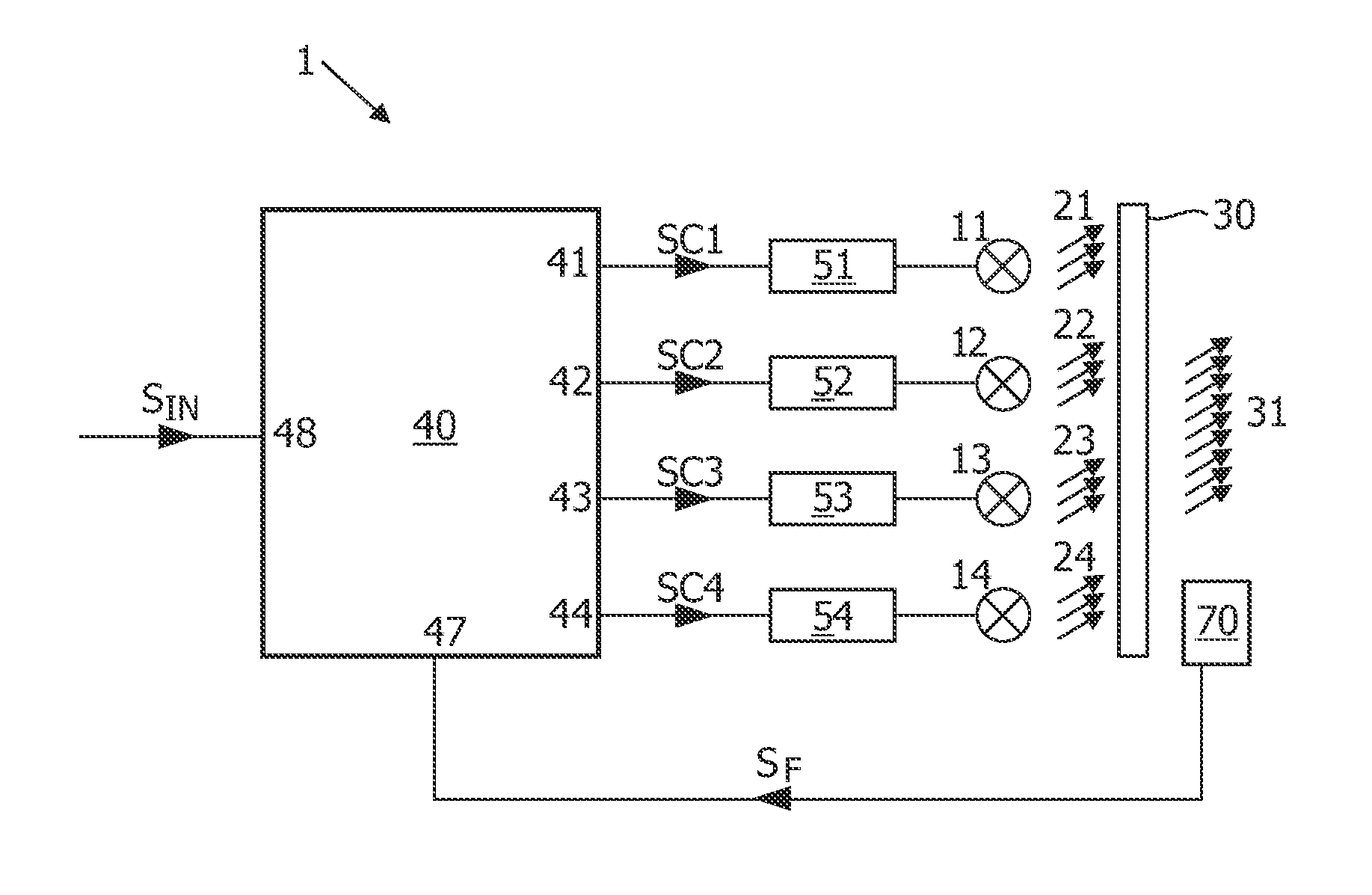
[0021]FIG. 1 schematically shows a lighting device 1 according to the present invention. The lighting device 1 comprises a plurality of light sources. In the illustrative embodiment, four light sources 11, 12, 13, 14 are shown, each producing light 21, 22, 23, 24 with mutually different colors, respectively, which may illustratively be red, green, blue, white, respectively. These different light contributions are mixed, for instance in an optical element 30, to produce mixed output light 31.

[0022]It is noted that each light source may be an individual LED, or an array or string of LEDs. Also, a light source may be of a different type.

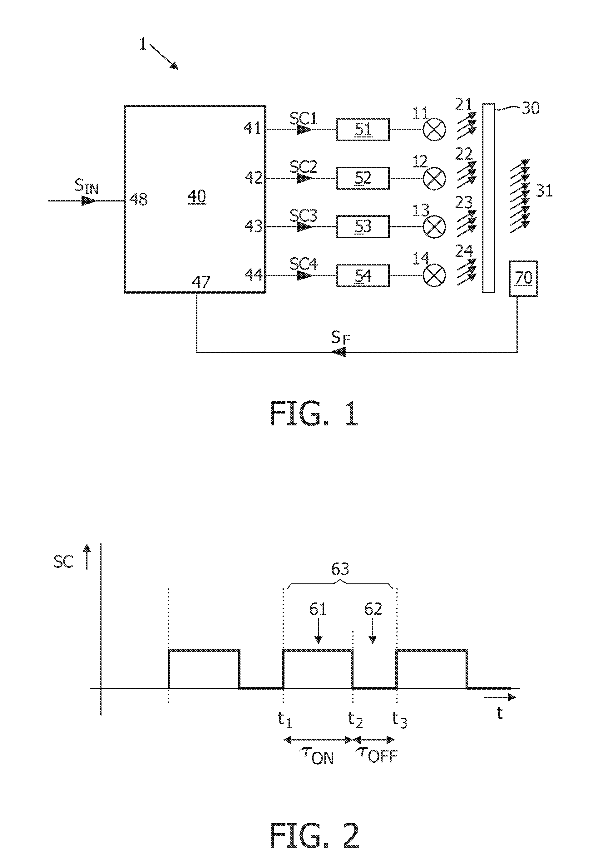
[0023]Each light source 11, 12, 13, 14 may be provided with an individual driver 51, 52, 53, 54, respectively. The device 1 comprises a controller 40 having control outputs 41, 42, 43, 44 coupled to control inputs of the respective drivers 51, 52, 53, 54. At these control outputs 41, 42, 43, 44, the controller 40 generates control signals SC1, SC2, SC3,...


PUM


Abstract

A lighting device (1) comprises a plurality of LEDs (11-14) producing light (21-24) of mutually different colors. The LEDs are driven in switching cycles (63) with a duty cycle controlled supply current of constant magnitude. In each switching cycle, each LED is first switched ON (61) and then switched OFF (62).
In a measuring mode, during one switching cycle (63B), all ON phases of all LEDs are briefly interrupted, except for one LED (11), so that a light sensor (70) measures the light from this one LED. This measurement can be used to adapt the duty cycle of this one LED. In the next switching cycle (63C), the interruption of the ON phases is compensated by extending the ON phases of all LEDs except said one LED, the extension having a duration equal to the duration (τD) of the interruption.

Description

FIELD OF THE INVENTION[0001]The present invention relates in general to the field of lighting using a plurality of dimmable light sources. Particularly, but not exclusively, the present invention relates to a lighting device comprising two or more dimmable light sources of mutually different color for producing output light with an output color that is a mixture of the colors of the contributing light sources. Since the light sources as used in practice are typically LEDs, the light sources will hereinafter simply be indicated as LEDs, but it is noted that this is not intended to limit the protective scope since the present invention can also be practiced with other types of light sources, for instance discharge lamps.BACKGROUND OF THE INVENTION[0002]A LED typically generates light within a narrow spectral range, which can be indicated as a point in a color space. With two LEDs of different color, the human observer will observe a resulting mix color having a color point on the line...

Claims


Application Information

Patent Timeline
IPC IPC(8): H05B37/02H05B44/00
CPCH05B33/0869H05B33/0818H05B45/22
Inventor VAN DER VEEN, GEERT WILLEMKWAKMAN, JOHANNES ANTONIUS
Owner KONINKLIJKE PHILIPS ELECTRONICS NV
Why Eureka
Try Eureka