Refrigeration compressor with internal cooling system

Inactive Publication Date: 2011-06-30
WHIRPOOL SA
View PDF3 Cites 3 Cited by
  • Summary
  • Abstract
  • Description
  • Claims
  • Application Information

AI Technical Summary

Benefits of technology

An objective of the invention is to provide an increase in the efficiency of hermetic refrigeration compressors, maximiz

Problems solved by technology

It is known that a large part of the losses of compressors are due to the overheating of gas in the path from the entry of the compressor up to the entry of the compr

Method used


Image

  • Refrigeration compressor with internal cooling system
  • Refrigeration compressor with internal cooling system
  • Refrigeration compressor with internal cooling system

Examples


Example

DETAILED DESCRIPTION OF THE DRAWINGS

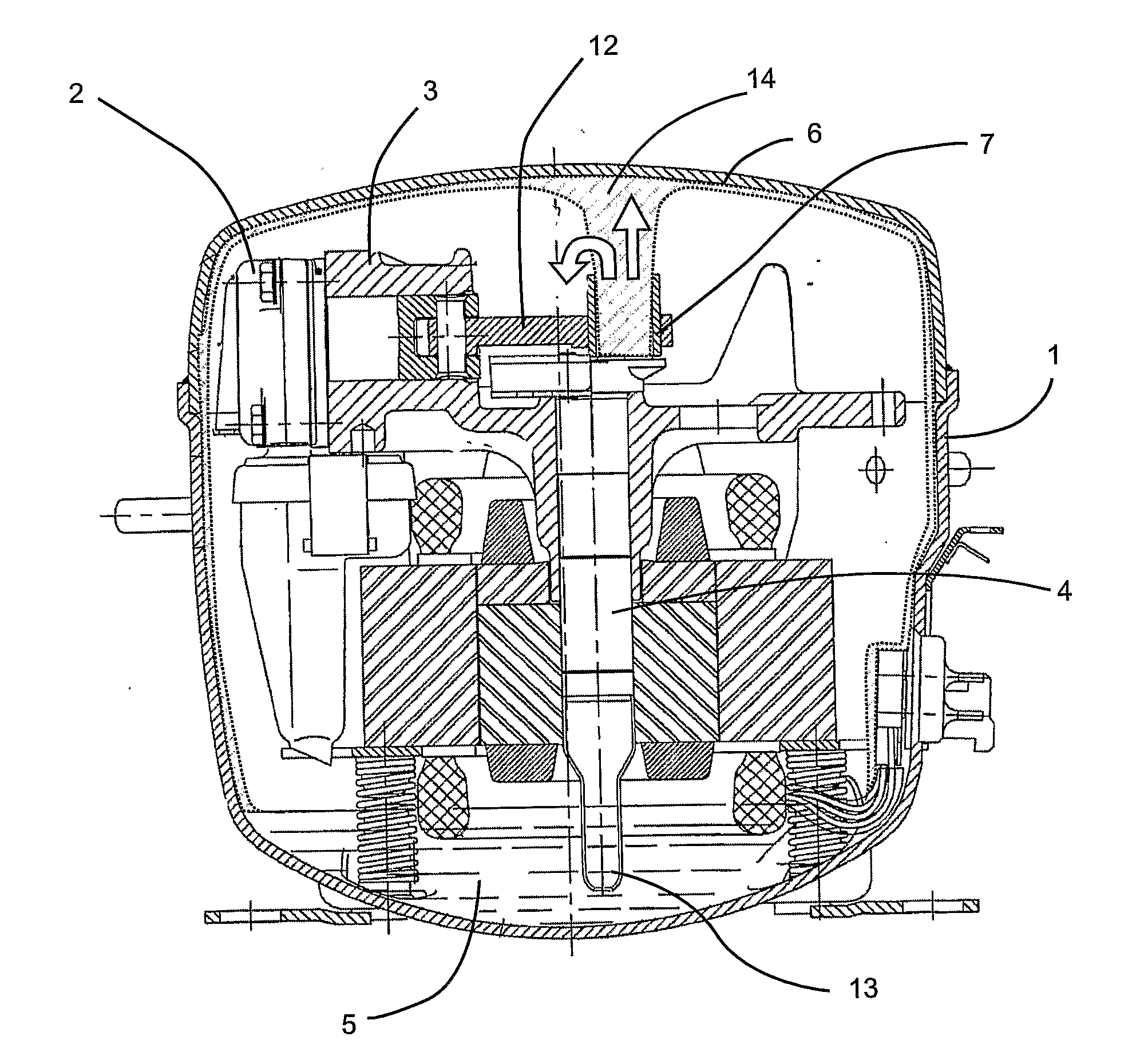
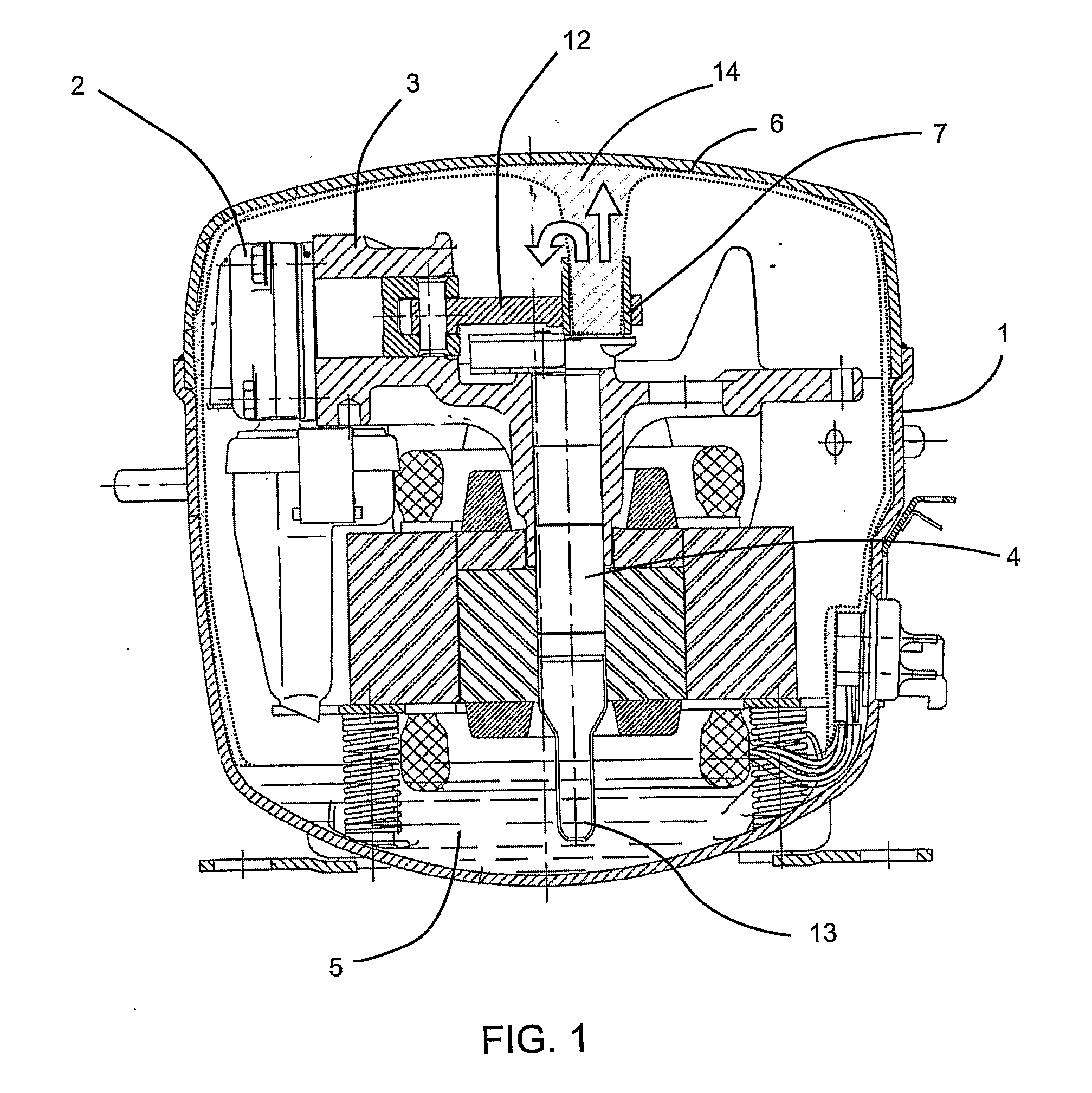
FIG. 1 depicts a compressor of the state of the art merely for comparison purposes with the present invention. This compressor of the hermetic refrigeration compressor type, with reciprocal movement does not have the internal cooling system of the present invention. This compressor is disposed inside the shell 1. The compressor comprises a cylinder that has a cylinder body 3 and a cylinder head 2, and a piston that performs an alternating movement inside the cylinder. In the lower portion of the compressor shell, an oil accumulating region 5 is formed in the shape of a well. The oil accumulating in this accumulation region originally has the purpose of lubricating the compressor parts, reducing the attrition between them and increasing the durability of the compressor.

This refrigeration compressor of the state of the art also has piston drive means, which are responsible for driving the alternating movement of the piston inside the cylinder, compr...


PUM


Abstract

A refrigeration compressor includes an internal cooling system. The compressor includes a compressor shell (1), inside of which are disposed a compression cylinder (2, 3), a piston that performs an alternating movement inside the cylinder, an oil accumulation region (5) in the lower part of the compressor shell, and piston drive means having a rotary shaft (4) oriented substantially vertically, with an upper end mounted to a piston drive cam (7). The compressor has a system for collecting the oil coming from the shaft (4), and expelled by the cam (7), in the upper part of the shell (1). This accumulated oil is drained over the compression cylinder (2, 3), so as to cool it, thus increasing the efficiency of the compressor.

Description

The present invention refers to hermetic refrigeration compressors, with reciprocal movement, which have means for collecting oil which is expelled by the drive shaft by way of the cam, in the upper part of the compressor shell. This accumulated oil is used to cool certain specific parts of the compressor block so as to increase the efficiency thereof. Thereafter, the oil returns to the bottom of the compressor.DESCRIPTION OF THE STATE OF THE ARTAttempts to improve the performance of refrigeration compressors are increasingly common, the main purpose being to reduce their energy consumption. It is known that a large part of the losses of compressors are due to the overheating of gas in the path from the entry of the compressor up to the entry of the compression cylinder. Another factor that reduces the performance of compressors is the inefficiency of gas compression, due to the high working temperature of the cylinder.Accordingly, with the aim of increasing the efficiency of the co...

Claims


Application Information

Patent Timeline
IPC IPC(8): F01B31/10
CPCF04B39/121F04B39/023F04B39/02F04B39/06F04B39/12
Inventor RIBAS JUNIOR, FERNANDO ANTONIOMAGNABOSCO, MATEUS
Owner WHIRPOOL SA
Why Eureka
Try Eureka