Environmentally protected switch for water activated devices

a technology of water activated devices and environmental protection, which is applied in the direction of life-saving, vessel safety, energy supply, etc., can solve the problems of inadvertent or accidental illumination of light sources, and the occurrence of accidental illumination

Active Publication Date: 2011-06-30
9609385 CANADA INC
View PDF6 Cites 6 Cited by
  • Summary
  • Abstract
  • Description
  • Claims
  • Application Information

AI Technical Summary

Benefits of technology

[0006]In accordance with the present invention, there is also provided a method for activating a signaling device powered by a battery and adapted for use with a conductive fluid, the method comprising providing an environmentally protected switch. The switch comprises a housing comprising an open end and a sensing element received within the housing along a longitudinal axis thereof and coupled to the signaling device for providing an electrical path connecting the battery and the signaling device, a tip of the sensing element substantially flush with the open end. The method further comprises submersing the switch into the fluid and agitating the switch to break a surface tension at an interface between the fluid and the open end, thereby enabling the fluid to penetrate the housing and an electrical current to flow within the sensing element for closing the electrical path and activating the signaling device.

Problems solved by technology

Still, a major drawback of these prior art devices is that the switch is not environmentally protected and in particular not splash resistant, therefore rendering the light source susceptible to accidental illumination resulting from activation of the switch by inadvertent splashing thereof.
Additionally, during winter months spray and humidity have a greater affinity for freezing which in many cases can also lead to inadvertent or accidental illumination.

Method used


Image

  • Environmentally protected switch for water activated devices
  • Environmentally protected switch for water activated devices
  • Environmentally protected switch for water activated devices

Examples


Embodiment Construction

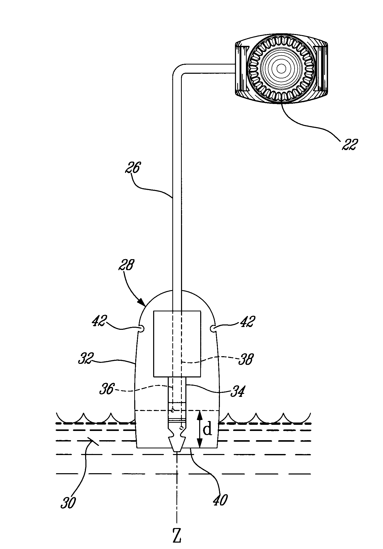
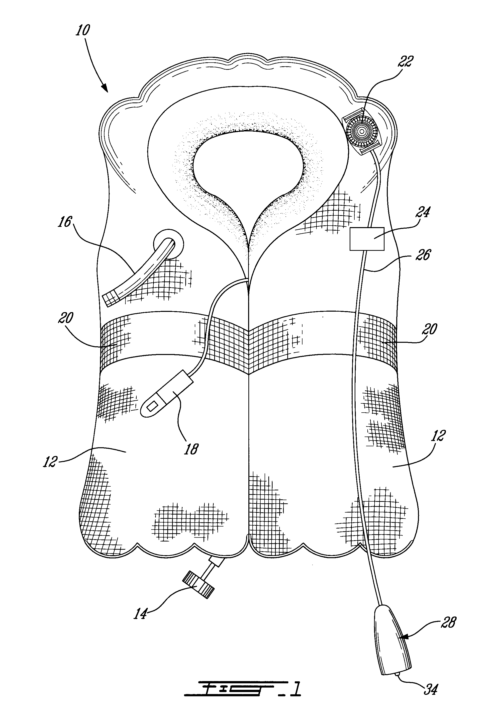
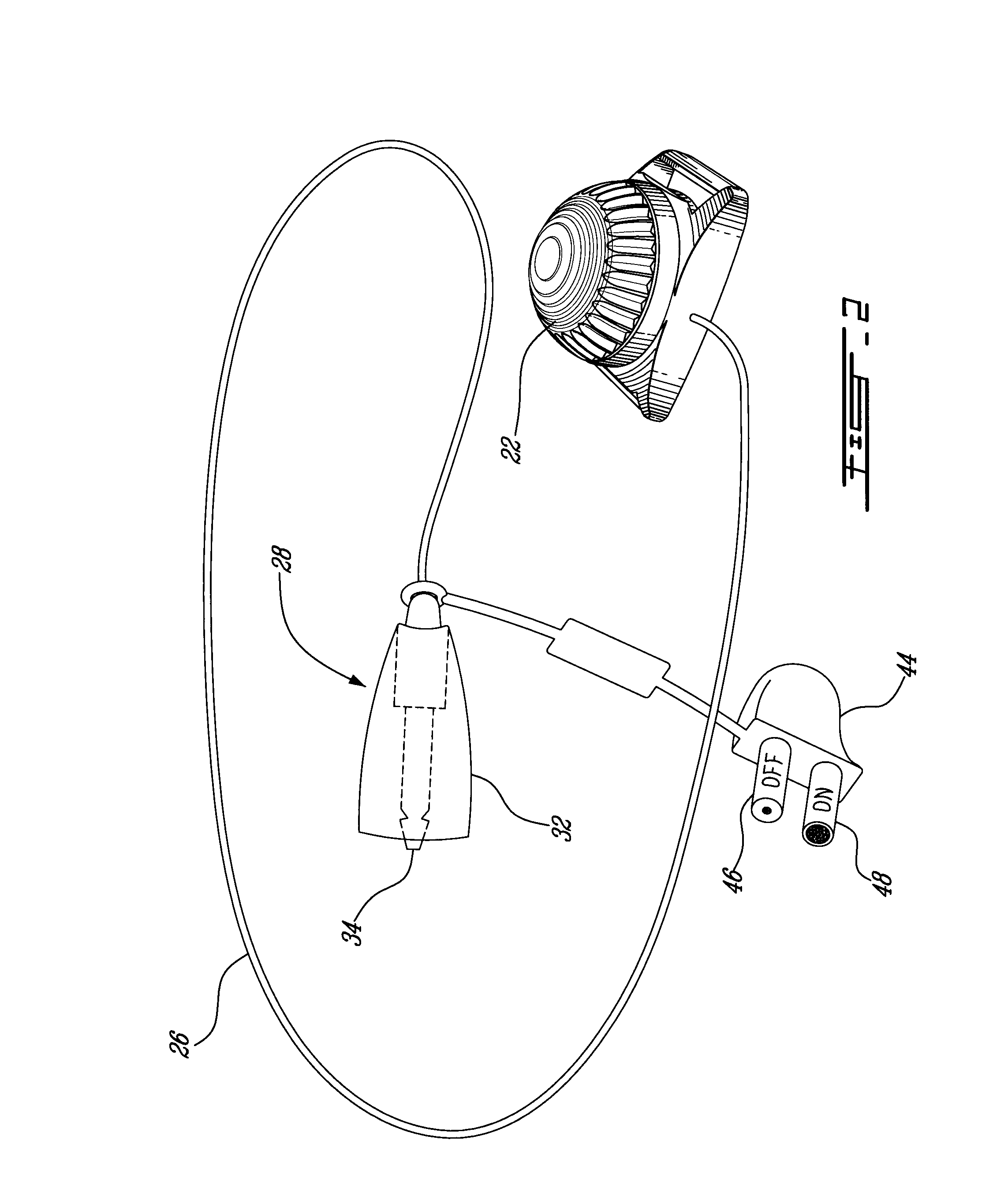
[0012]Referring now to FIG. 1, and in accordance with an illustrative embodiment of the present invention, a life vest, generally referred to using the reference numeral 10, will now be described. The life vest 10 is comprised of one or more chambers as in 12, which are filled with a buoyant material (not shown). In the case of an inflatable vest, the buoyant material is a gas, such as CO2 or air, which is introduced into the chamber(s) from a cylinder or the like (not shown), typically activated by means of a rip cord 14. Additionally, a back up oral inflation tube 16 is provided in order to maintain buoyancy or inflate the vest 10 when the cylinder is empty or inoperable. In order to improve the wearer's chances of being discovered, the outer visible part of the life vest 10 is typically manufactured from a bright material in yellow or day-glow orange. Additionally, the life vest 10 is equipped with a whistle 18 for generating an audible signal, reflective strips as in 20 and a si...


PUM


Abstract

An environmentally protected switch for activating a signalling device, such as a light source, powered by a battery and adapted for use with a conductive fluid. The switch comprises an open ended housing and a sensing element received within the housing along a longitudinal axis thereof, a tip of the sensing element being substantially flush with the open end. The sensing element is coupled to the signalling device for providing an electrical path connecting the battery and the signalling device. Upon submersion of the switch into the fluid and agitation of the switch, a surface tension at an interface between the fluid and the open end is broken and fluid penetrates the housing up to a predetermined depth to enable an electrical current to flow within the sensing element for closing the electrical path and activating the signalling device.

Description

CROSS REFERENCE TO RELATED APPLICATIONS[0001]This application claims priority, under 35 U.S.C. §119(e), of U.S. provisional application Ser. No. 61 / 079,211, filed on Jul. 9, 2008, which is incorporated herein by reference in its entirety.FIELD OF THE INVENTION[0002]The present invention relates to an environmentally protected switch for water activated devices, such as safety lights.BACKGROUND OF THE INVENTION[0003]In order to provide persons in need of rescue with a prompt response in emergency situations, the prior art teaches signaling devices for use with personal flotation devices, such as inflatable life vests and the like. Such signaling devices, which typically comprise a small yet bright light source powered by a battery pack, improve the visibility of a person stranded in water by generating a noticeable flashing signal or strobe. A submersible switch may be included to activate the light source when placed in a conductive fluid, such as water. Still, a major drawback of t...

Claims


Application Information

Patent Timeline
Patent Type & Authority Applications(United States)
IPC IPC(8): H01H1/20
CPCB63B2209/02B63C9/20F21L4/00F21V23/0414H01H29/28F21Y2101/02G08B21/088G08B21/20F21V31/00F21Y2115/10
Inventor FORD, TIMOTHY D.F.
Owner 9609385 CANADA INC
Why Eureka
Try Eureka