Remote drive for disconnector/isolator used in switchgear

a technology of disconnector/isolator and remote drive, which is applied in the direction of contact mechanism, switch power arrangement, air-break switch, etc., can solve the problems of operator danger right in front of the circuit breaker, personal danger to the operator's safety, and significant injury, including burns, to achieve the effect of reducing the risk of operator injury

Active Publication Date: 2011-06-30
SCHNEIDER ELECTRIC USA INC
View PDF14 Cites 13 Cited by
  • Summary
  • Abstract
  • Description
  • Claims
  • Application Information

AI Technical Summary

Benefits of technology

[0005]To keep the operator a safe distance away from the switchgear during a racking operation in which the disconnector is placed in a service or isolated position or in optionally a grounded position, the present disclosure provides a motor that causes movable contacts of a motorized drive system to move between corresponding fixed contacts for connection to the busbars within the switchgear and to primary connectors of the circuit breaker fixedly mounted within the switchgear. The motor can be remotely controlled by a wired or wireless control device that permits the operator to be located a safe distance away from the switchgear and even outside the room in which the switchgear is located during a racking operation. On / off statuses of position switches placed in a path of a moving structure as the racking operation is performed can be used to stop the motor in response to the motorized drive system transitioning from one position to another.

Problems solved by technology

Racking such high-capacity circuit breakers is a procedure wrought with personal danger to the operator's safety.
A possibility always exists that an explosion will occur due to an arc flash, causing significant injury, including burns, or even death to the operator.
Existing techniques have attempted to keep the operator a distance away from the circuit breaker while racking it into or out of the switchgear equipment; however, the operator is still required to be present in the same room and sometimes remain in close proximity to the circuit breaker within the blast range of an arc flash hazard.
This puts the operator dangerously right in front of the circuit breaker and in the blast zone of an arc flash.

Method used


Image

  • Remote drive for disconnector/isolator used in switchgear
  • Remote drive for disconnector/isolator used in switchgear
  • Remote drive for disconnector/isolator used in switchgear

Examples


Embodiment Construction

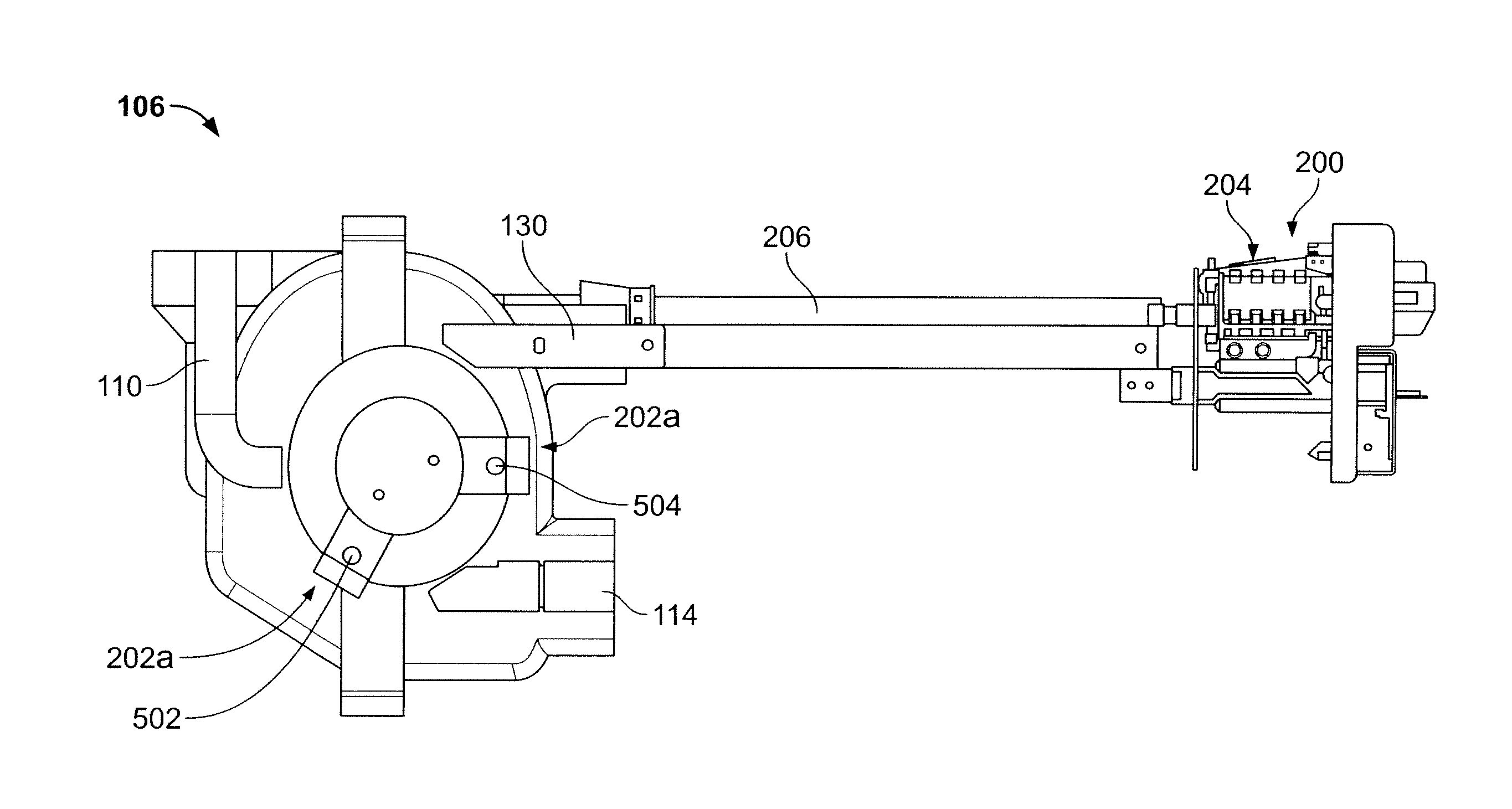
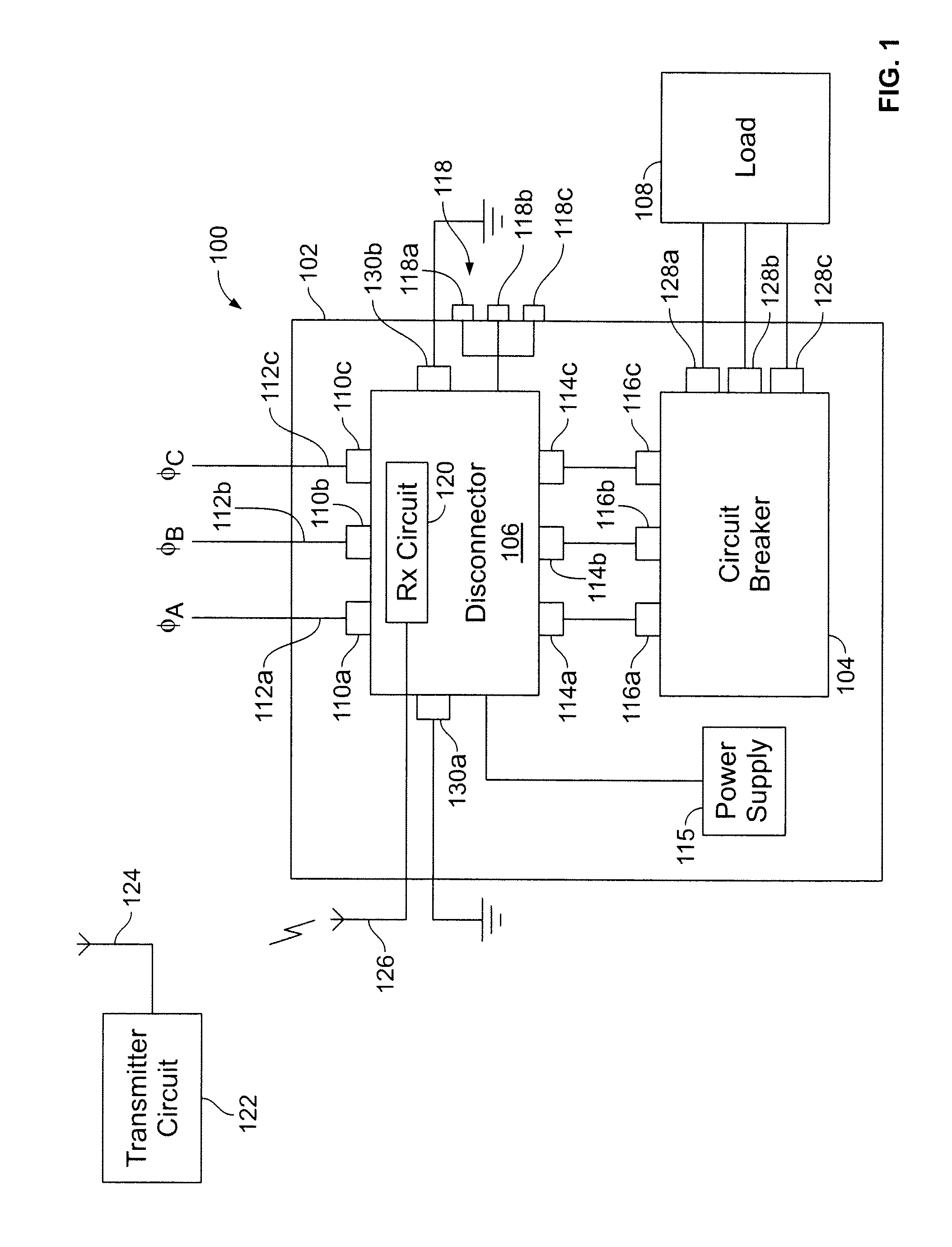
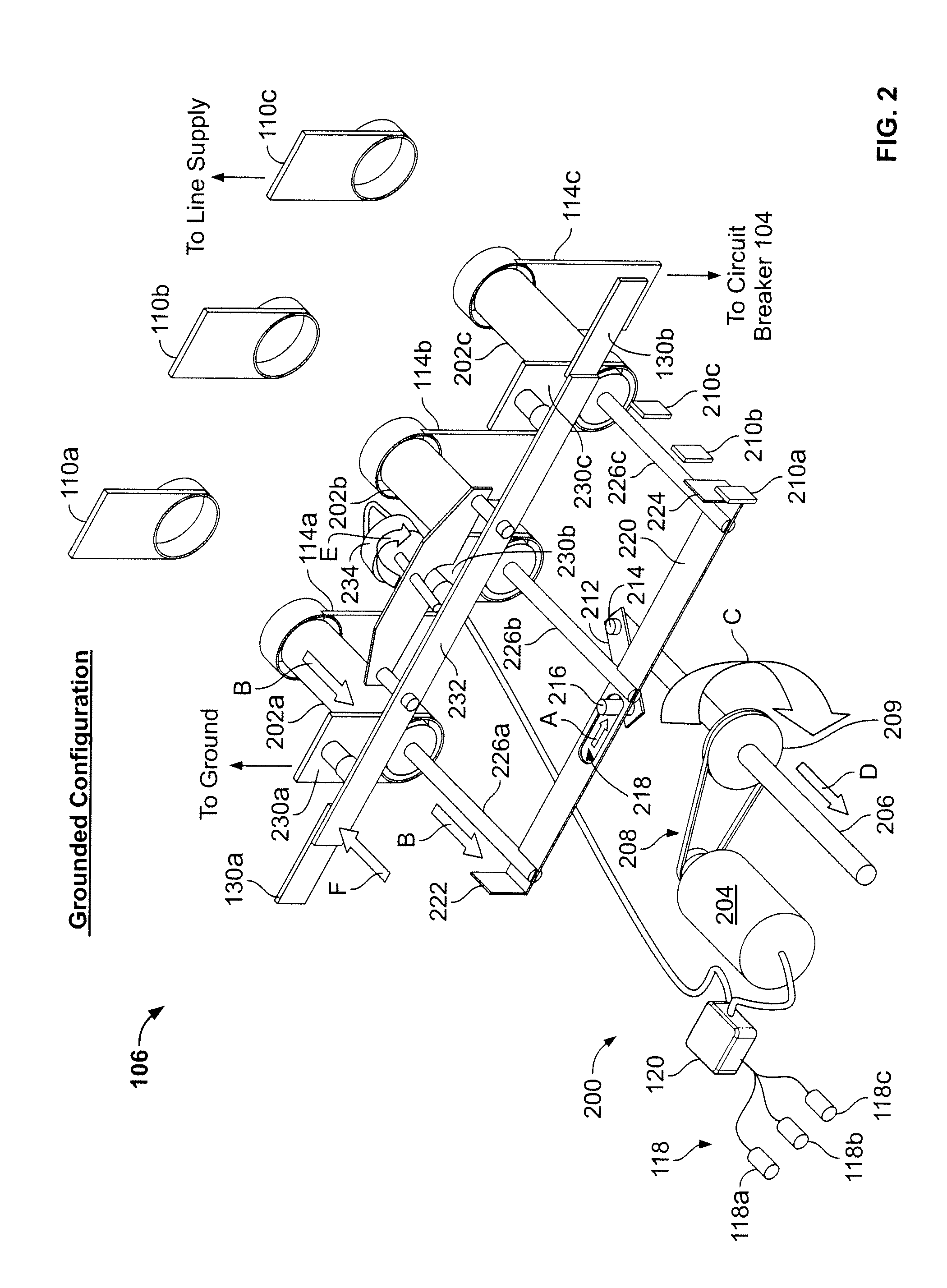
[0016]FIG. 1 is a functional block diagram of an electrical switchgear apparatus 100 (variously called switchgear or a switchboard) that resembles a large standing cabinet. The switchgear 100 can have a high, medium, or low voltage rating as defined by the American National Standards Institute (ANSI) or can refer to a switchboard as defined in Underwriters Laboratory Standard UL891. The switchgear 100 has a conventional rigid metal frame or cabinet 102 for housing one or more circuit breakers 104 and a disconnector 106 (also called an isolator) interposed between the circuit breaker 104 and three electrical phases ØA, ØB, ØC of an electrical line supply that is conventionally supplied external to the switchgear 100. The circuit breaker 104 is fixed to the metal frame 102 of the switchgear 100 by screws or bolts or the like. In this example, the switchgear 100 lacks a draw-in / draw-out racking mechanism with movable rails for racking the circuit breaker 104 into and out of the switchg...


PUM


Abstract

A remotely controlled, motorized drive system for a disconnector used in switchgear. An operator pushes a button on a remote control, which signals a receiver in the disconnector to engage a motor that is coupled to a drive shaft. The drive shaft causes movable contacts of the disconnector to be moved into engagement or out of engagement with sets of fixed contacts in the switchgear that are connected to the line supply and to the circuit breaker that is bolted into the switchgear. One set of contacts is electrically coupled to the line supply, which can carry up to three phases of current. Another set of contacts is connected to corresponding terminals of the circuit breaker. A second motor controls movement of a grounding bar that grounds the circuit breaker to earth. Indicator lights on the switchgear panel indicate the position of the disconnector for visual confirmation of the same.

Description

FIELD OF THE INVENTION[0001]The present disclosure relates to racking mechanisms for a disconnector / isolator used in electrical switchgear, and, more particularly, to a remotely controlled motorized internal mechanism for a disconnector / isolator used in electrical switchgear equipment.BACKGROUND[0002]Electrical switchgear equipment (sometimes just called switchgear or a switchboard) house very large and heavy circuit breakers that protect loads that can consume thousands of amps of current. The procedure for making or breaking the electrical connections inside the switchgear between the circuit breaker and connectors in the switchgear is referred to as racking. Racking such high-capacity circuit breakers is a procedure wrought with personal danger to the operator's safety. A possibility always exists that an explosion will occur due to an arc flash, causing significant injury, including burns, or even death to the operator. There are at least two ways to carry out a racking operatio...

Claims


Application Information

Patent Timeline
Patent Type & Authority Applications(United States)
IPC IPC(8): H01H3/32
CPCH01H3/26H01H2003/268H01H31/24H02B13/02
Inventor TRUSSLER, RICHARD M.LEE, GREGORY B.
Owner SCHNEIDER ELECTRIC USA INC
Why Eureka
Try Eureka