Lift, in particular traction sheave lift

A technology for pulling pulleys and elevators, which is applied in the field of elevators and can solve problems such as increasing the height of shafts

Inactive Publication Date: 2003-12-10
蒂森升降机有限责任公司
View PDF2 Cites 11 Cited by
  • Summary
  • Abstract
  • Description
  • Claims
  • Application Information

AI Technical Summary

Problems solved by technology

However, this construction leads to an increase in the shaft height in the direction of the shaft length used for the elevator car, because the frame and the drive respectively require additional shaft height

Method used


Image

  • Lift, in particular traction sheave lift
  • Lift, in particular traction sheave lift
  • Lift, in particular traction sheave lift

Examples


Embodiment Construction

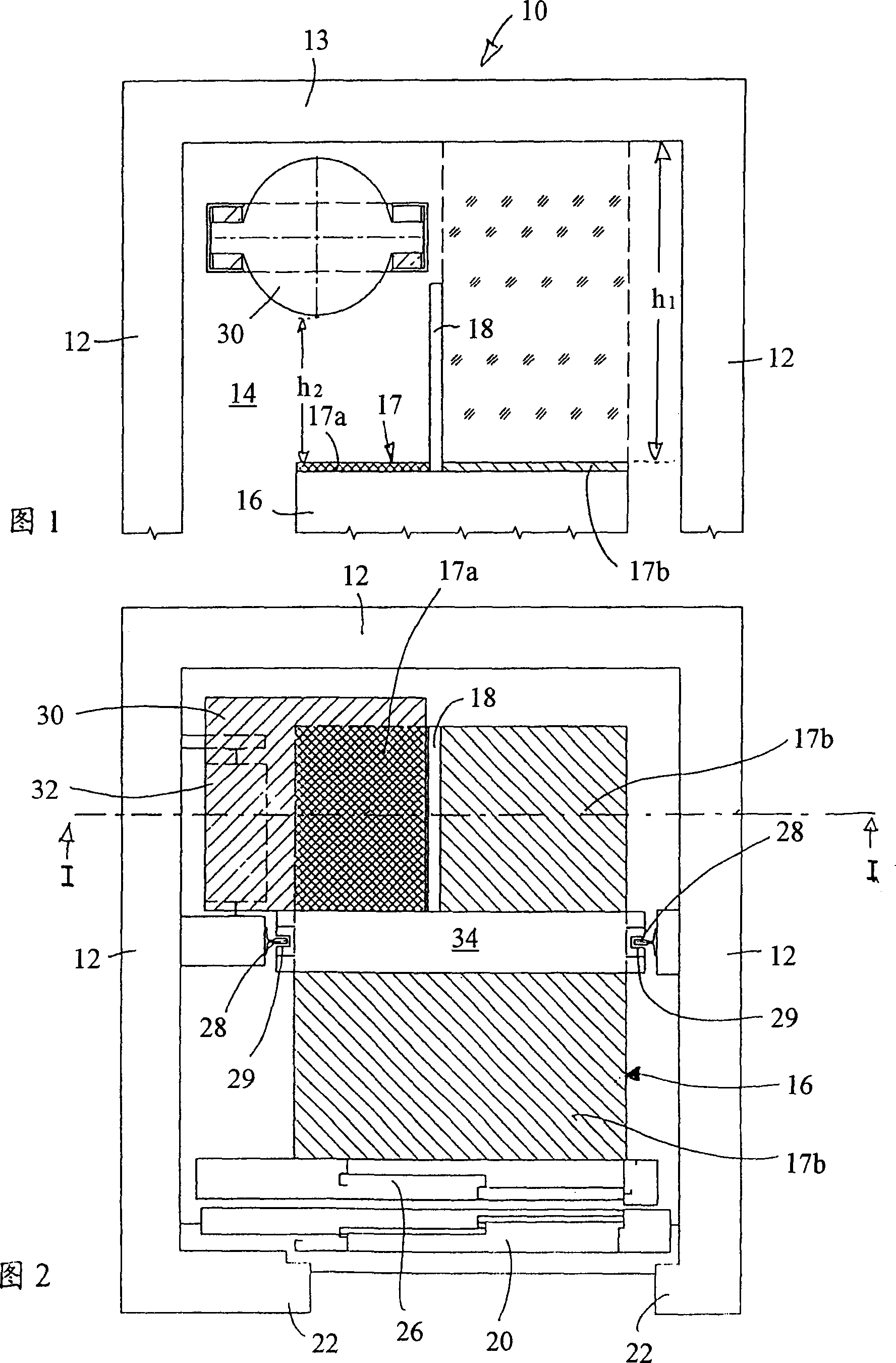
[0032] Figure 1 shows a schematic cross-sectional view of the top of an elevator 10 of the present invention. The elevator 10 comprises an elevator car 16 which is located in an elevator shaft 14 and has an elevator car roof 17 . In Figure 1, the elevator car 16 is in its upper rest position, only the top of which is shown.

[0033] The elevator shaft 14 of the elevator 10 is delimited by a shaft wall 12 and a shaft roof 13 . On the elevator platform on the shaft wall 12 there is provided a door opening defined by a door side 22 which is closed by a shaft door 20 (see FIG. 2 ). The elevator car is provided with an elevator car door 26 which is used to open the passage between the elevator car and the elevator platform and which can be opened together with the shaft door 20 .

[0034] In the elevator shaft 14 the elevator car 16 is equipped with a drive so that the elevator car is moved vertically in the elevator shaft 14 . The drive device comprises a drive machine 30 which i...


PUM


Abstract

An elevator with an elevator cage guided in a shaft between a shaft head and a shaft pit, having an elevator cage roof and an elevator cage base and a drive, which is connected by at least one hauling cable with the elevator cage, whereby in particular for performing maintenance work the elevator cage roof is designed to be accessible, whereby the drive is arranged at least partly in the shaft head over a first region of the elevator cage roof and the accessibility of the elevator cage roof is restricted to a second region.

Description

technical field [0001] The present invention relates to elevators and, more particularly, to traction sheave elevators. Background technique [0002] Usually, an elevator with a traction sheave drive comprises an elevator car, which is arranged in the elevator shaft, and in the upper part there is a drive mechanism area, in which the control, transmission and other elevator components are arranged. Here, the cables on one side of the traction sheave run down to the elevator car, and the cables on the other side run to the counterweight. Therefore, even during the operation of the elevator, maintenance personnel can also stand on the roof of the elevator car to carry out maintenance or installation work. The elevator car extends to the lower edge of the part arranged on top of the shaft. In general, such elevators with the transmission area outside the shaft in the shaft roof have at least a roller support for the return pulley of the traction cable, which is also arranged ...

Claims


Application Information

Patent Timeline
Patent Type & Authority Patents(China)
IPC IPC(8): B66B9/00B66B11/00
CPCB66B11/0045
Inventor 冈特·路透汉斯·裴迪南德·弗尔·V·肖利汉斯·昂特加瑟于尔根·舒尔茨冈瑟·布利克莱哈特马特·温曼
Owner 蒂森升降机有限责任公司
Why Eureka
Try Eureka