

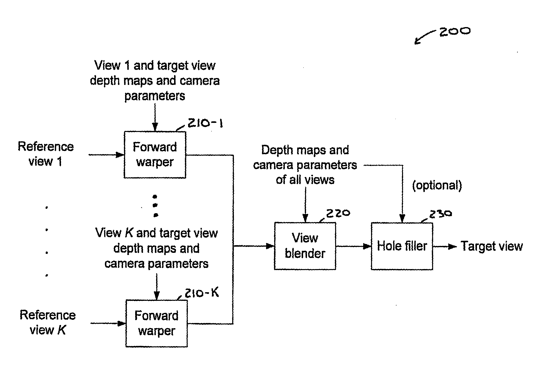
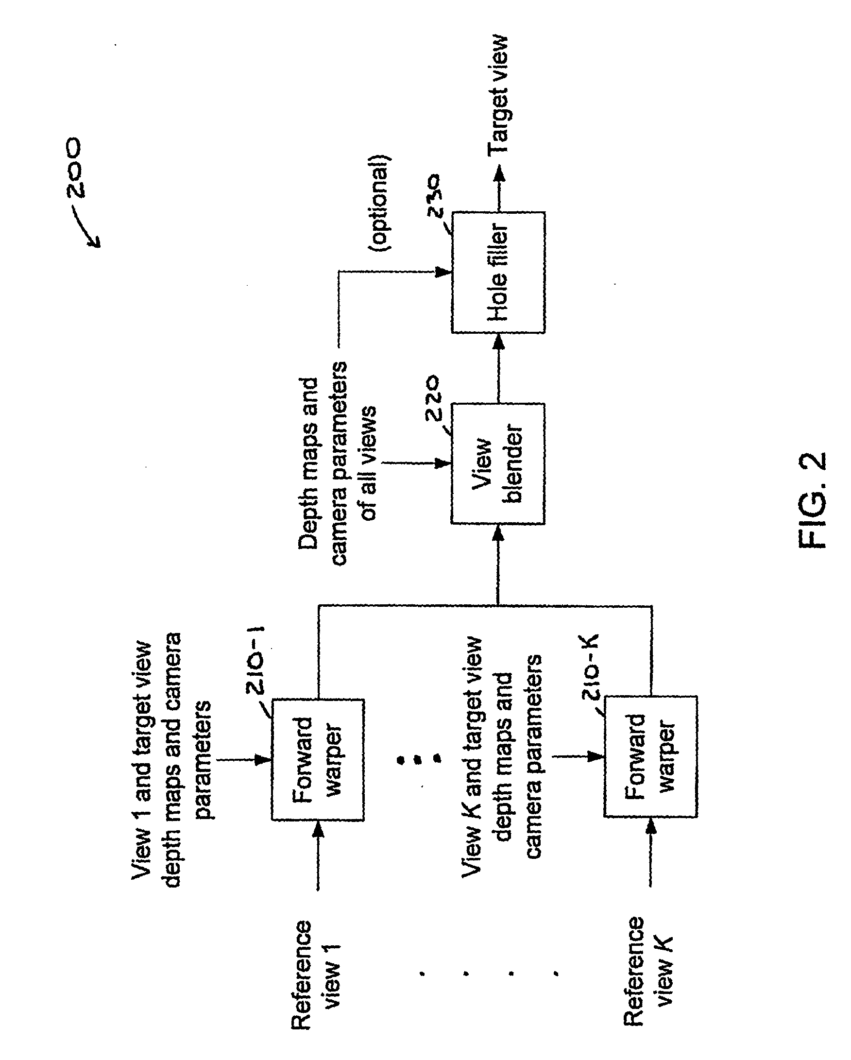
View synthesis with heuristic view blending
a synthesis and view technology, applied in the field of coding systems, can solve the problems of image details being lost, and the scheme in the two previous embodiments might appear too complicated for some applications
- Summary
- Abstract
- Description
- Claims
- Application Information
AI Technical Summary
Benefits of technology
Problems solved by technology
Method used
Image

Examples
embodiment 1
ews
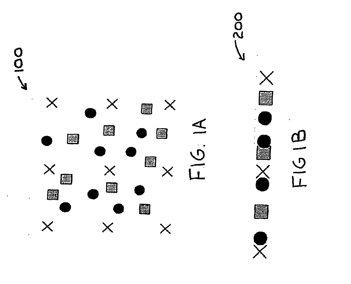
[0090]For simplification, rectified view synthesis is used as an example, i.e., estimate the target pixel value from the candidate pixels on the same horizontal line (FIG. 1B).
[0091]For each target pixel, warped pixels within ±a pixels distance from this target pixel are chosen as candidate pixels. The one with maximum depth level maxY (closest to the virtual camera) is found. Parameter a here is crucial. If it is too small, then pinholes will appear. If it is too large, then image details will be lost. It can be adjusted if some prior knowledge about the scene or input depth precision is known, e.g., using the variance of the depth noise. If nothing is known, value 1 works most of time.
[0092]In a typical Z-buffering algorithm, the candidate of maximum depth level (i.e., closest to the camera) will determine the pixel value at the target position. Here, the other candidate pixels are also kept as long as their depth levels are quite close to the maximum depth, i.e., (Y≧maxY−thres...
embodiment 2
d Views
[0099]The blending scheme in FIG. 8 is easily extended to the case of non-rectified views. The only difference is that candidate pixels will not be on the same line of the target pixel (FIG. 1A). However, the same principle to select candidate pixels based on their depth and their distance to the target pixel can be applied.
[0100]The same interpolation scheme, i.e., Equation (6), can also be used. For more precise weighting, W(ri,i) can be further determined at the pixel level. For example, using the angle determined by 3D points Ori-Pi-Os, where Pi is the 3D position of the point corresponding to pixel I (estimated with Equation (3)), Ori and Os are the optic focal centers of the reference view ri and the synthesized view respectively (known from camera parameters). We recommend setting W(ri,i)=1 / angle(Ori-Pi-Os) or W(ri,i)=cosq(angle(Ori-Pi-Os)), for q>2. FIG. 9 shows the angle 900 determined by 3D points Ori-Pi-Os, in accordance with an embodiment of the present principles...
embodiment 3
n with Up-Sampling
[0101]The schemes in the two previous embodiments might appear to be too complicated for some applications. There are ways to approximate them for fast implementation. FIG. 10A shows a simplified up-sampling implementation 1000 for the case of rectified views, in accordance with an embodiment of the present principles. In FIG. 10A, “+” represents new target pixels inserted at half-pixel positions. FIG. 10B shows a blending scheme 1050 based on Z-buffering, in accordance with an embodiment of the present principles. At step 1055, a new sample is created at a half-pixel position at each horizontal line (e.g., up-sampling per FIG. 10A). At step 1060, from candidate pixels within ±½ from the target pixel, the one with the maximum depth level is found and its color is applied as the color of the target pixel Cs (i.e., Z-buffering). At step 1065, down-sampling is per performed with a filer (e.g., {1, 2, 1}.
[0102]In the synthesized view, a new target pixel is first insert...
PUM
 Abstract
Description
Claims
Application Information