View synthesis correction method and device

A technology of view synthesis and correction method, which is applied in image communication, optics, instruments, etc., and can solve the problems of complex implementation and poor display image quality.

Inactive Publication Date: 2015-12-30
CHONGQING DROMAX PHOTOELECTRIC
View PDF5 Cites 21 Cited by
  • Summary
  • Abstract
  • Description
  • Claims
  • Application Information

AI Technical Summary

Problems solved by technology

[0004] However, it is very complicated to calculate the offset distance repeatedly and perform multiple corrections, and the grating lamination error cannot be avoided. In this way, the quality of the image displayed by the subsequent 3D module with grating lamination error is very poor.

Method used


Image

  • View synthesis correction method and device
  • View synthesis correction method and device
  • View synthesis correction method and device

Examples


Embodiment 1

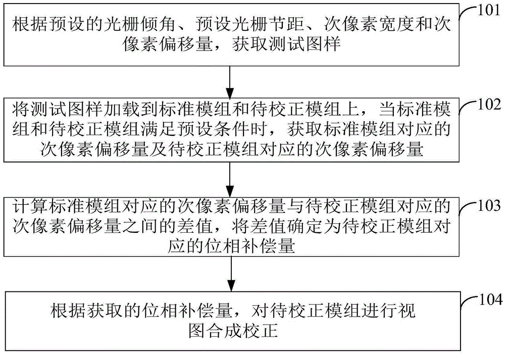
[0062] see Figure 1A , an embodiment of the present invention provides a view synthesis method. The method specifically includes the following steps:

[0063] Step 101: Obtain a test pattern according to the preset grating inclination angle, preset grating pitch, sub-pixel width and sub-pixel offset;

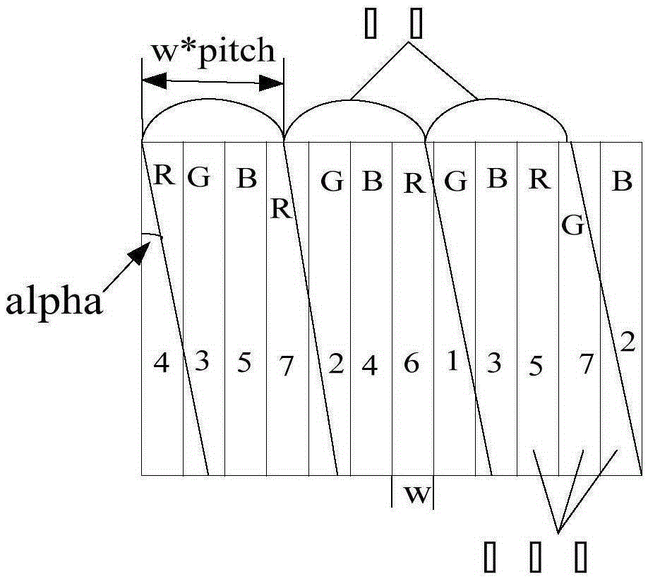
[0064] An RGB (Red-Green-Blue, red-green-blue) pixel in an image consists of three sub-pixels of R, G and B. Such as Figure 1B As shown in , the preset inclination angle alpha of the grating is the angle between the grating and the sub-pixel. The letter w is the width of the sub-pixel, w*pitch is the preset grating pitch, and pitch is the ratio between the preset grating pitch and the sub-pixel width.

[0065] The above-mentioned operation of obtaining the test pattern can be realized through the following first and second methods, including:

[0066] In the first way, according to the preset grating tilt angle, preset grating pitch, sub-pixel width and sub-pixel offset, t...

Embodiment 2

[0103] see figure 2 , an embodiment of the present invention provides a view synthesis correction device, the device is used to implement the above view synthesis correction method. Specifically, the device includes:

[0104] The first acquiring module 201 is configured to acquire a test pattern according to a preset grating tilt angle, a preset grating pitch, a sub-pixel width and a sub-pixel offset;

[0105] The second acquisition module 202 is used to load the test pattern onto the standard module and the module to be corrected, and when the standard module and the module to be corrected meet the preset conditions, obtain the corresponding sub-pixel offset of the standard module and The sub-pixel offset corresponding to the module to be corrected;

[0106] The calculation module 203 is used to calculate the difference between the sub-pixel offset corresponding to the standard module and the sub-pixel offset corresponding to the module to be corrected, and determine the d...


PUM


Abstract

The invention provides a view synthesis correction method and device. The method includes the following steps that: a test image sample is obtained according to a preset grating inclination angle, a preset grating pitch, sub pixel width and sub pixel offset; the test image sample is loaded onto a standard module set and a module set to be corrected; when the standard module set and the module set to be corrected meet preset conditions, sub pixel offset corresponding to the standard module set and sub pixel offset corresponding to the module set to be corrected are obtained; a difference value between the sub pixel offset corresponding to the standard module set and the sub pixel offset corresponding to the module set to be corrected is calculated, and the difference value is determined as phase compensation quantity corresponding to the module set to be corrected; and view synthesis correction is performed on the module set to be corrected according to the phase compensation quantity. According to the view synthesis correction method and device of the invention, the phase compensation quantity corresponding to the module set to be corrected can be obtained, and view synthesis correction can be carried out according to the phase compensation quantity when the module set to be corrected displays an image in a follow-up stage even if grating attachment errors exist on the module set to be corrected, and therefore, the quality of image display of the module set to be corrected can be improved.

Description

technical field [0001] The present invention relates to the technical field of three-dimensional display, in particular, to a method and device for view synthesis correction. Background technique [0002] At present, in the lamination process of gratings in the production and manufacture of 3D (Three-Dimensional, three-dimensional) modules, the uncertainty of the relative position between the gratings and the screen leads to the deviation of the best viewing position and the poor quality of the view displayed by the 3D modules And other problems limit the application of stereoscopic display. Therefore, how to perform view synthesis correction according to the offset of grating lamination has become an urgent problem to be solved. [0003] The current existing technology does not perform view synthesis correction for 3D modules, but corrects grating lamination during the process of producing 3D modules. Specifically, when producing 3D modules, alignment marks are set on the...

Claims


Application Information

Patent Timeline
Patent Type & Authority Applications(China)
IPC IPC(8): G02B27/22H04N13/04
CPCG02B30/27
Inventor 陆小松张涛李春
Owner CHONGQING DROMAX PHOTOELECTRIC
Why Eureka
Try Eureka