Iron head

a technology of iron head and spherical head, which is applied in the field of iron head, can solve the problems of difficult to obtain a strong impact feeling, and achieve the effects of reducing the total weight of the iron head, enlarge the sweet area without increasing the total weight, and increasing the partial weigh

Inactive Publication Date: 2011-06-30
SHIMAZAKI HIDEO
View PDF82 Cites 14 Cited by
  • Summary
  • Abstract
  • Description
  • Claims
  • Application Information

AI Technical Summary

Benefits of technology

[0033]In the first aspect of the present invention, the iron head is provided with the first hollow portion and the second hollow portion on the toe side and the heel side of the middle portion, respectively, thereby reducing a total weight of the iron head. Accordingly, it is possible to enlarge a sweet area without increasing the total weight. Further, it is possible to increase a partial weight on the toe side and the heel side, thereby increasing the sweet area of the iron head. In the iron head in the first aspect, the hollow portion is not provided behind the middle portion. Accordingly, it is possible to obtain a strong hitting impact feeling when hitting a ball at the middle portion.
[0034]In the eleventh aspect of the present invention, the iron head is provided with the hollow portion extending from the toe side toward the heel side of the middle portion. Accordingly, it is possible to reduce the total weight of the iron head. Therefore, it is possible to increase a size of the iron head without increasing the total weight thereof. In addition, it is possible to increase a partial weight on the toe side and the heel side of the iron head without increasing the total weight of the iron head, thereby increasing the sweet area. In the iron head, the face plate has the thickness at the middle portion greater than that of the toe side and the heel side. Accordingly, it is possible to obtain a strong hitting impact feeling when hitting a ball at the middle portion.

Problems solved by technology

When the golf club having the iron head hits a ball at a middle portion thereof, it is difficult to obtain a strong impact feeling due to the hollow portion formed behind the middle portion and the small thickness of the face plate at the middle portion of the iron head.

Method used


Image

  • Iron head
  • Iron head
  • Iron head

Examples


first embodiment

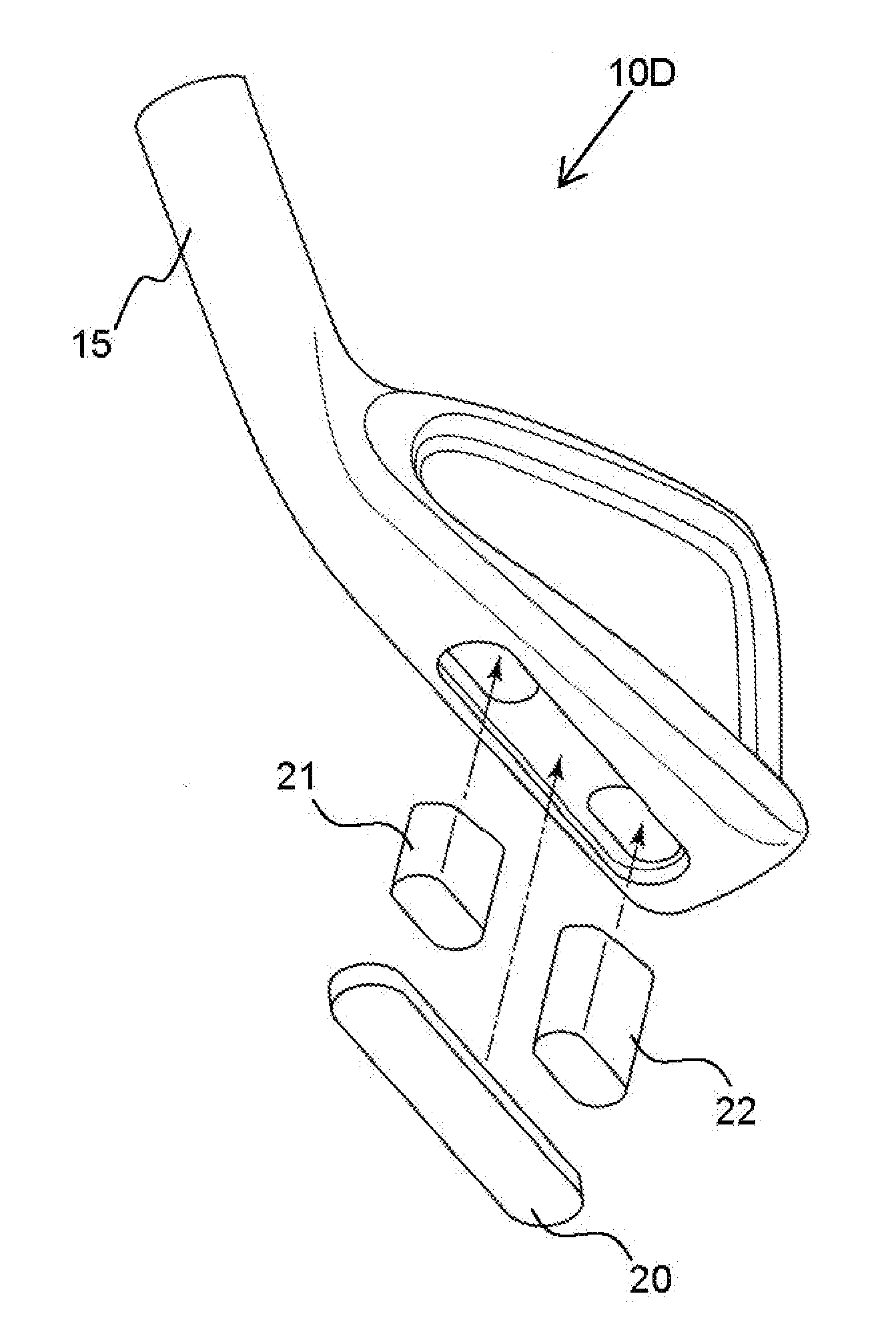
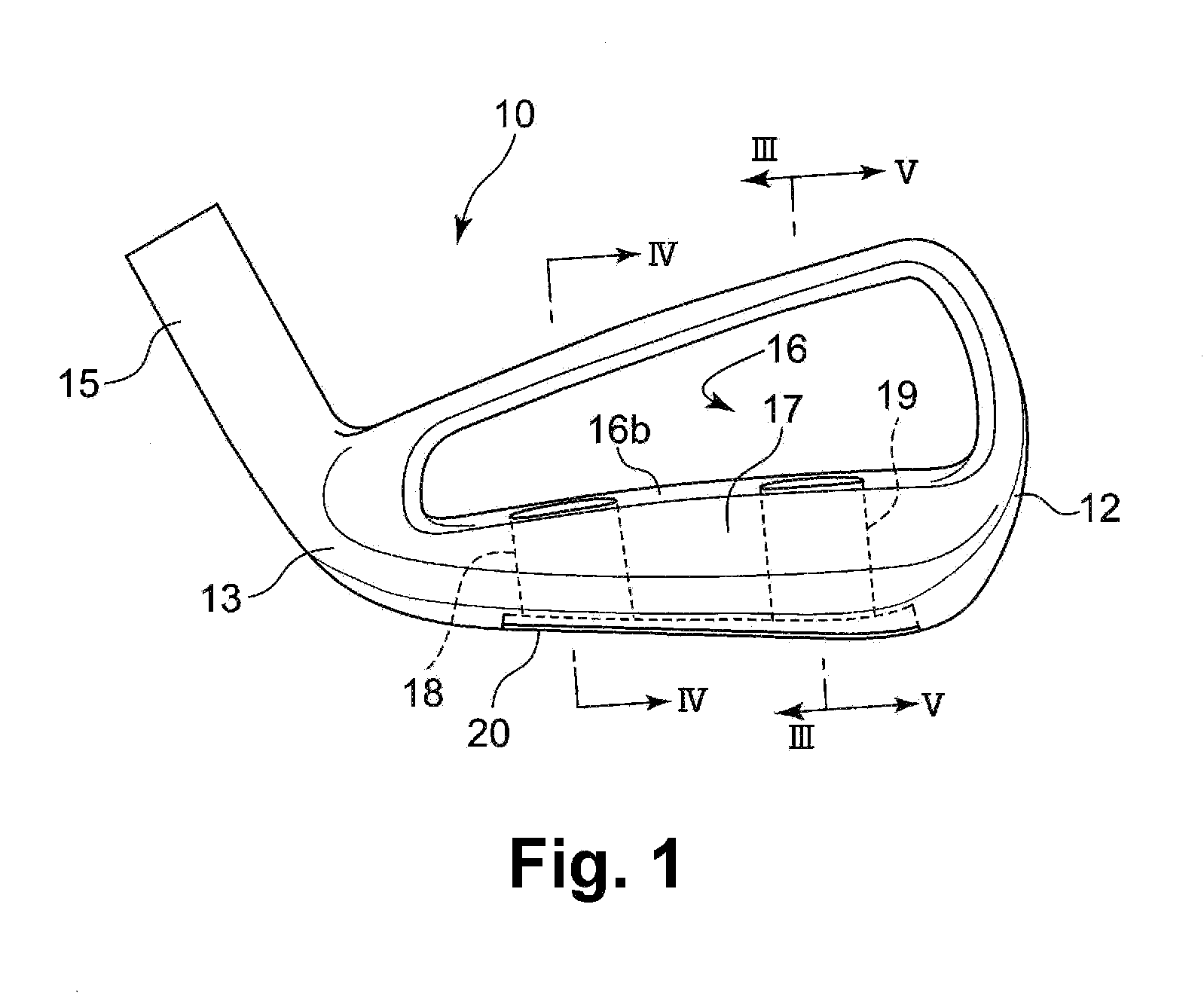
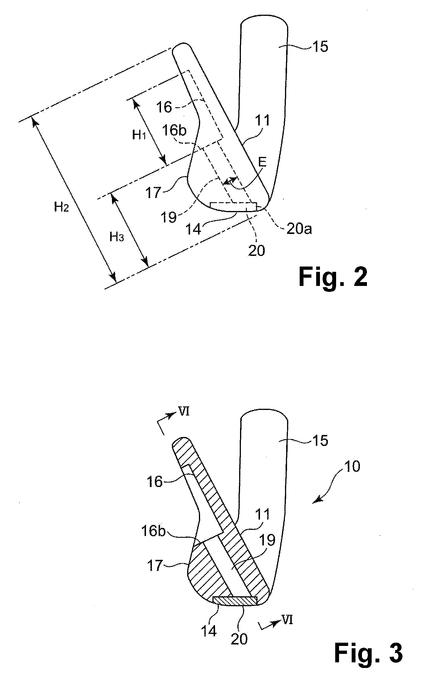
[0072]FIGS. 1 through 6 show an iron head 10 according to a first embodiment of the present invention. The iron head 10 is provided with a striking face 11 for hitting a ball, a toe side 12, a heel side 13, a sole surface 14, and a hosel 15 for connecting a shaft. Further, the iron head 10 is provided with a cavity portion 16 disposed in an upper portion of a backside surface thereof; a protruding portion 17 disposed at a lower portion of the backside surface thereof and projecting backward; a first hollow portion 18 disposed on the heel side 13 of the protruding portion 17 and penetrating from a bottom surface 16b of the cavity portion 16 to the sole surface 14; a second hollow portion 19 disposed on the toe side of the protruding portion 17; and a bottom lid 20 disposed on the sole surface to close the hollow portions 18 and 19.

[0073]As shown in FIG. 6, the cavity portion 16 is recessed from a rear side of the iron head to the striking surface side thereof not only at an upper edg...

second embodiment

[0083]FIGS. 7 and 8 show an iron head 10A according to the second embodiment of the present invention. According to the first embodiment, the width W1 of the middle portion M in the toe to heel direction is substantially same from the upper end thereof to the lower end thereof. According to the second embodiment, instead of the hollow portions 18 and 19 in the first embodiment, the iron head 10A is provided with a hollow portion 18A disposed away from a hollow portion 19A by a distance gradually increasing from the upper surface of the protruding portion toward the sole surface.

[0084]It is desirable that the hollow portion 18A and the hollow portion 19A have a distance therebetween, at the top end thereof, being same as the width W1 mentioned above. Further, at the bottom end, it is desirable that the distance between the hollow portion 18A and the hollow portion 19A is equal to or less than 1.2 times, especially equal to or less than 1.1 times, of the distance between the hollow po...

third embodiment

[0085]In the first and second embodiments, the hollow portions 18, 19, 18A, and 19A have a width E, which is the thickness thereof in the vertical direction to the face surface. The width E is substantially same from the top end to the bottom end of the hollow portions 18, 19, 18A, and 19A. As shown in FIG. 9, in an iron head 10B according to the third embodiment, each of hollow portions 18B (not shown) and 19B has a thickness gradually increasing from the top end of the hollow portions toward the bottom end thereof. Further, the hollow portions 18B and 19B have a thickness, at the upper end thereof, being same as the width E in the first and second embodiments. It is desirable that the thickness of the bottom end of the hollow portions 18B and 19B is equal to or less than twice, especially equal to or less than 1.2 times, of that of the upper end thereof. Other configurations of the third embodiment are same as the first embodiment, and same reference numerals denote same component...


PUM


Abstract

An iron head is provided with a recess portion provided in an upper portion of a backside surface thereof, and a protruding portion provided at a lower portion of the backside surface. A first hollow portion is provided on a heel side from a bottom surface of a recess portion to a sole surface; and a second hollow portion is disposed on a toe side. The first hollow portion and the second hollow portion do not exist behind a sweet area. The first hollow portion and the second hollow portion may be filled with a shock absorber formed of a rubber or an elastomer.

Description

CROSS-REFERENCE TO RELATED APPLICATIONS[0001]This is a continuation application of a prior application Ser. No. 12 / 507,266, filed Jul. 22, 2009, pending.BACKGROUND OF THE INVENTION AND RELATED ART STATEMENT[0002]The present invention relates to an iron head for an iron type golf club. More particularly, the present invention relates to an iron head having a hollow portion.[0003]An iron type golf club includes a shaft and an iron head disposed at a distal end of the shaft, so that a striking face of the iron head hits a ball. The shaft is inserted and fixed into a hosel formed in the iron head. A side of the iron head where the hosel is formed is referred to as a heel, and an opposite side of the iron head, i.e., a distal end side thereof, is referred as a toe. A bottom side of the iron head facing a ground surface is referred to as a sole. A plurality of grooves, i.e., score lines, is formed in the striking face of the iron head with a certain distance therebetween in a vertical dir...

Claims


Application Information

Patent Timeline
Patent Type & Authority Applications(United States)
IPC IPC(8): A63B53/04
CPCA63B53/047A63B53/0475A63B59/0092A63B2209/00A63B2053/0433A63B2053/0491A63B2053/0408A63B60/54A63B53/0408A63B53/0433A63B60/02A63B53/04
Inventor SHIMAZAKI, HIDEO
Owner SHIMAZAKI HIDEO
Why Eureka
Try Eureka