Container internal lock mechanism

a technology of internal locking and container, which is applied in the direction of rigid containers, transportation and packaging, packaging, etc., can solve the problems of accidental damage of external locks, unfavorable deterrence of access to contents within containers,

a technology of internal locking and container, which is applied in the direction of rigid containers, transportation and packaging, packaging, etc., can solve the problems of accidental damage of external locks, unfavorable deterrence of access to contents within containers,

US20110162418A1Inactive Publication Date: 2011-07-07UNION PACIFIC RAILROAD

Image

  • Container internal lock mechanism
  • Container internal lock mechanism
  • Container internal lock mechanism

Examples


Embodiment Construction

)

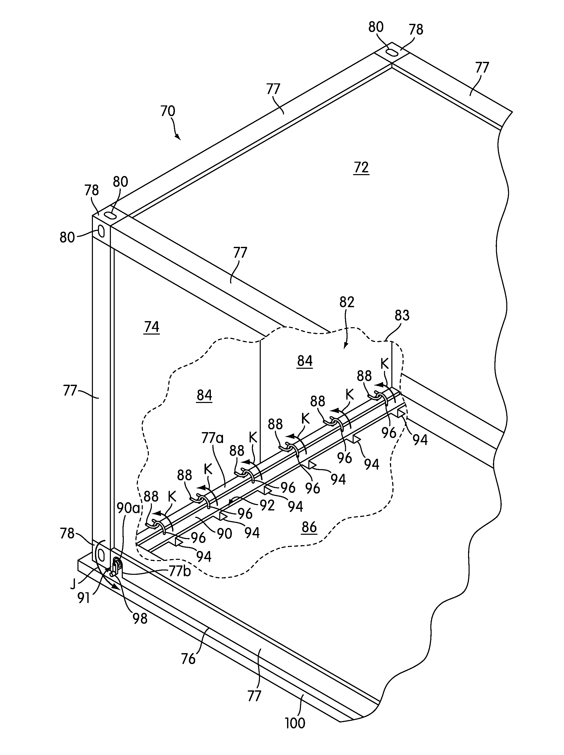
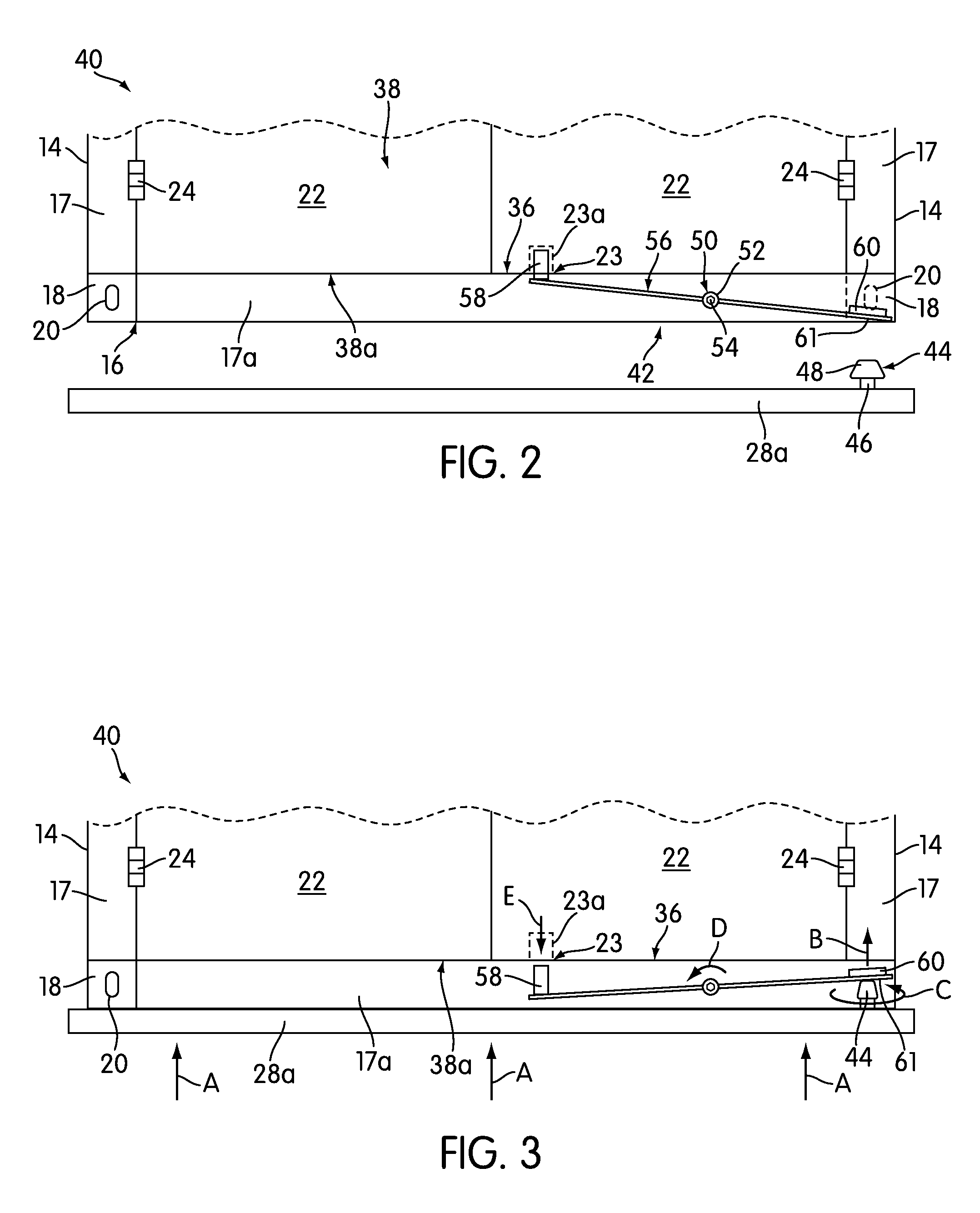
It is a goal of the present invention to provide an internal, mechanical lock mechanism, for at least one door of a container, that is biased towards a locked position when the door is closed. Generally, the internal lock mechanism(s) are designed such that they prevent opening of the doors and access to the contents in the containers (e.g., by intruders or thieves), such as during transportation or storage. The internal lock mechanism may be automatically unlocked to an unlocked position through contact with a contact portion by a contacting structure of an object. Such a contacting structure may be a twist lock that is used with a chassis, for example. In this case, “automatically” unlocking the lock mechanism refers to moving the mechanism to an unlocked position when contact is made with a contact portion of the lock mechanism. For purposes of this disclosure, a “chassis” is defined as an under frame device on which a container is mounted for transport, such as through a rail y...


PUM


Abstract

Disclosed are internal lock mechanisms for doors of intermodal containers. The lock mechanisms include a lock member that moves between a locked position engaging a door to lock the door in the closed position and an unlocked position disengaged from the door to permit the door to move from the closed position to the open position. At least a portion of the lock mechanism is provided within or adjacent to the sill. In one instance, the lock member is biased toward the locked position, and a contact portion on a bottom of the container is contacted to unlock it. The lock mechanism may be accessed via connection openings in a corner fitting, for example. In another instance, hooks and hook receiving members are provided within an interior of the container, and rotated along a rotatable shaft between the two positions.

Description

BACKGROUND1. Field of InventionThe present invention is generally related to providing an internal locking mechanism for locking doors of containers.2. Description of Related ArtWhen transporting goods or products in containers (such as intermodal containers) via a railway system, the doors to the containers are usually locked to prevent access to the contents therein via accident or theft. Often, external locking devices are provided to lock the doors. FIG. 1 illustrates an example of an external locking device. However, these locking devices may not necessarily deter access to the contents within the container. Also, at times, external locks may be accidentally damaged (e.g., by contact with another container) when moving or stacking, for example.SUMMARYOne aspect of the present invention provides an intermodal container having: at least a top wall, a bottom wall, side walls, at least one door and a sill adjacent a bottom end of the at least one door. The at least one door is mova...

Claims


Application Information

Patent Timeline
07 Jul 2011
Publication
US20110162418A1
IPC
E05B65/14; E05B15/00; E05B17/20
CPC
B65D90/0026; B65D2211/00; B65D90/008; Y10T70/5155; Y10T70/70; Y10T70/80
Inventors
RONCI, WAYNE L.; HERNANDEZ, ADRIAN A.