Apparatuses and Methods for Determining Potential Energy Stored in an Electrochemical Cell

a technology of potential energy and electrochemical cells, applied in cell components, primary cell maintenance/service, instruments, etc., can solve the problems of inconvenient use, lack of interactive display packages, and inability to meet consumer needs, and achieve the effect of facilitating a reading of potential energy stored

Active Publication Date: 2011-07-07
CCL LABEL INC
View PDF23 Cites 26 Cited by
  • Summary
  • Abstract
  • Description
  • Claims
  • Application Information

AI Technical Summary

Benefits of technology

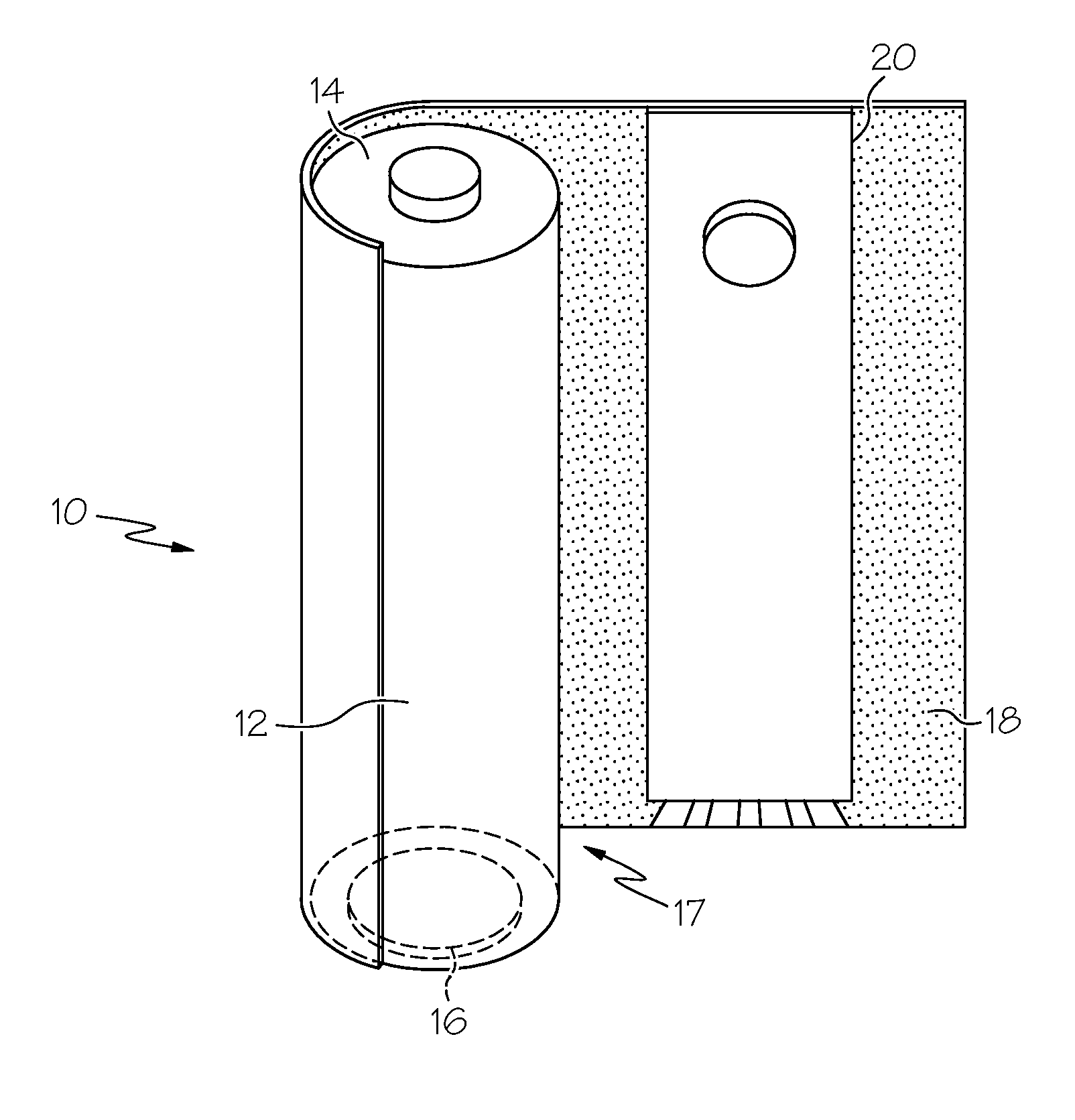
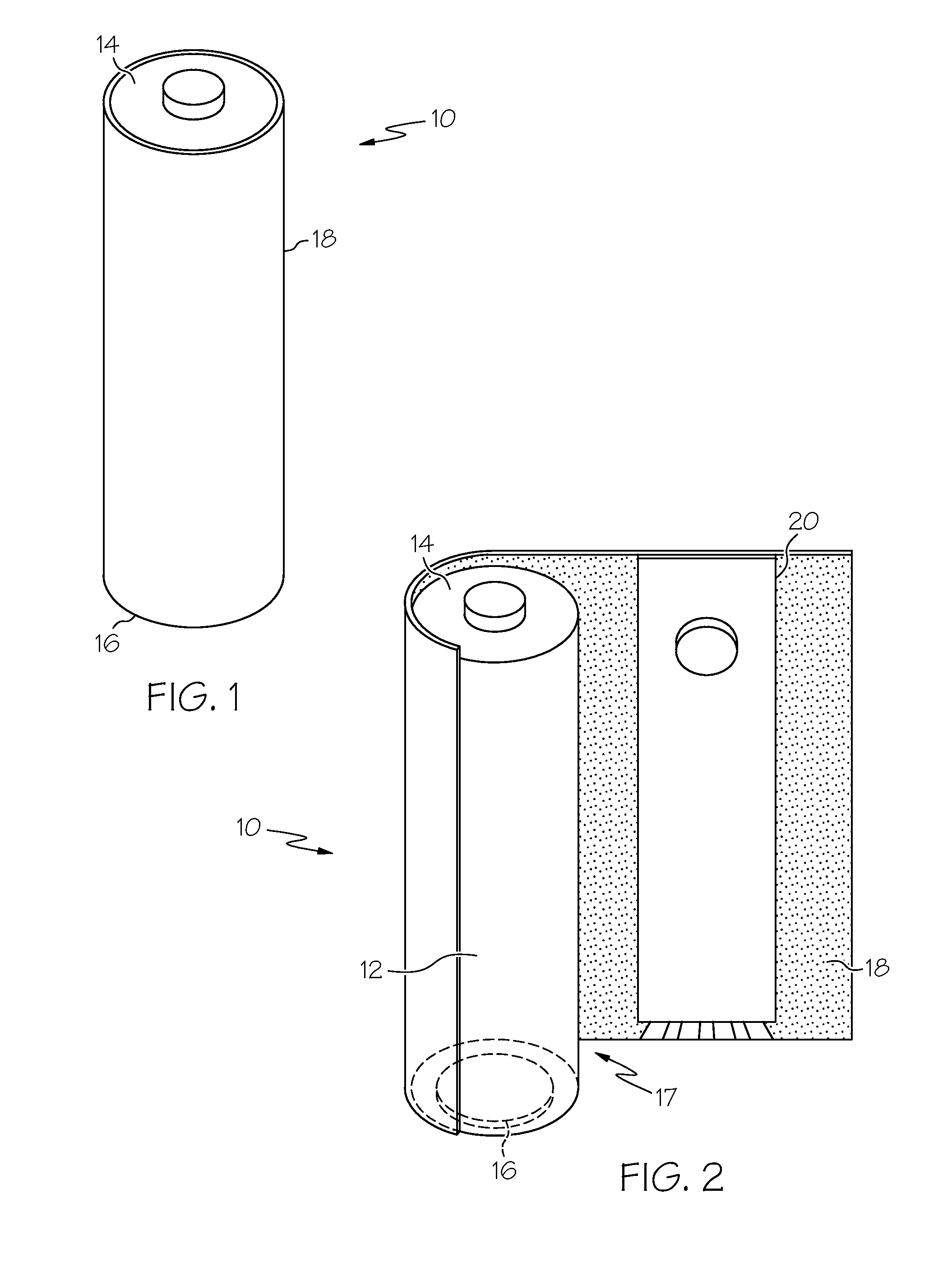
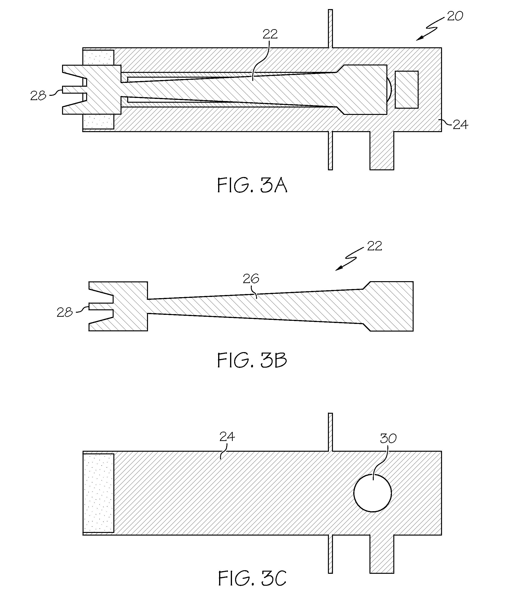
[0007]In accordance with one embodiment, a battery which includes a first terminal, a second terminal, an outer layer, and a power indicator apparatus is provided. The power indicator apparatus includes an electrical conductor and a mechanical switch. The electrical conductor is configured to be in continuous electrical communication with the first terminal. The mechanical switch is configured to be actuated by an application of pressure at a single location, and upon actuation, to place the electrical conductor in electrical communication with the second terminal such that the power indication apparatus can facilitate a reading of a potential energy stored in the battery.

Problems solved by technology

During these periods of storage or low level usage, the potential energy stored in a battery dissipates.
However, an issue in the market place is that apparatus and methods currently utilized to determine the potential energy in a battery, is not consumer friendly.
Currently, the marketplace is lacking a display package that is interactive, allowing consumer to check a battery's potential energy without having to actually purchase the battery.

Method used


Image

  • Apparatuses and Methods for Determining Potential Energy Stored in an Electrochemical Cell
  • Apparatuses and Methods for Determining Potential Energy Stored in an Electrochemical Cell
  • Apparatuses and Methods for Determining Potential Energy Stored in an Electrochemical Cell

Examples


Embodiment Construction

[0029]The apparatuses and methods disclosed in this document are described in detail by way of examples and with reference to FIGS. 1-11. Unless otherwise specified, like numbers in FIGS. 1-11 indicate references to the same, similar, or corresponding elements throughout FIGS. 1-11. It will be appreciated that modifications to disclosed and described examples, arrangements, configurations, components, elements, apparatuses, methods, materials, etc. can be made and may be desired for a specific application. In this disclosure, any identification of specific shapes, materials, techniques, arrangements, etc. are either related to a specific example presented or are merely a general description of such a shape, material, technique, arrangement, etc. Identifications of specific details or examples are not intended to be, and should not be, construed as mandatory or limiting unless specifically designated as such. Selected examples of apparatuses and methods for determining a potential en...


PUM

PropertyMeasurementUnit
potential energyaaaaaaaaaa
electricalaaaaaaaaaa
pressureaaaaaaaaaa

Abstract

A battery includes a first terminal, a second terminal, an outer layer, and a power indicator apparatus. The power indicator apparatus comprises an electrical conductor and a mechanical switch. The electrical conductor is configured to be in continuous electrical communication with the first terminal. The mechanical switch is configured to be actuated by an application of pressure at a single location, and upon actuation, to place the electrical conductor in electrical communication with the second terminal such that the power indication apparatus can facilitate a reading of a potential energy stored in the battery. Methods of determining a potential energy stored in the battery are also provided herein.

Description

CROSS-REFERENCE TO RELATED APPLICATION[0001]The present application claims the benefit of U.S. Provisional Application No. 61 / 293,016 filed Jan. 7, 2010, which is incorporated herein by reference in its entirety.TECHNICAL FIELD OF THE INVENTION[0002]This field of this invention relates generally to determining the potential energy stored in an electrochemical cell and, more particularly, to determining the amount of electrical power stored in a battery.BACKGROUND OF THE INVENTION[0003]Electrochemical cells such as batteries are common sources of electrical power for many consumer, commercial, and industrial applications. Batteries are often purchased and stored for periods of time before being used. In addition, batteries may be periodically used in a device which may slowly drain energy from the electrochemical cell. During these periods of storage or low level usage, the potential energy stored in a battery dissipates. Therefore, a battery can have a finite usable life. Apparatus ...

Claims


Application Information

Patent Timeline
Patent Type & Authority Applications(United States)
IPC IPC(8): G01N27/416
CPCH01M2/022H01M6/5044Y02E60/50H01M10/488H01M8/0293Y02E60/10H01M50/107
Inventor JANOUSEK, PAULYANES, ALFREDO
Owner CCL LABEL INC
Why Eureka
Try Eureka