Roller reefing boom for sailing ships

a technology for sailing ships and booms, applied in the field of sail booms, can solve the problems of poor sailing properties, poor position, and loss of shap

Inactive Publication Date: 2011-07-14
WALDHAUSER KURT +1
View PDF8 Cites 3 Cited by
  • Summary
  • Abstract
  • Description
  • Claims
  • Application Information

AI Technical Summary

Benefits of technology

[0008]The aim of the invention was to provide a largely automatable boom sail roller reefing installation, for example for a mainsail, which can be operated by hand via cable pulls, such as is conventional for relatively small vessels, or, for relatively large vessels, can be operated electrically or hydraulically from the control position allowing secure positioning and stowing of

Problems solved by technology

This has the drawback that three-dimensionally profiled, bulging, i.e. aerodynamically advantageously cut, sails cannot be rolled up correctly on account of the partially different cloth lengths to be rolled up and, in the reefed, i.e. partly rolled-up, state, lose shape and have a poor position and thus poor sailing properties.
Flat-cut sails, such as are used as a remedy for roller reefing booms, also with horizontal sail batten

Method used


Image

  • Roller reefing boom for sailing ships
  • Roller reefing boom for sailing ships
  • Roller reefing boom for sailing ships

Examples


Embodiment Construction

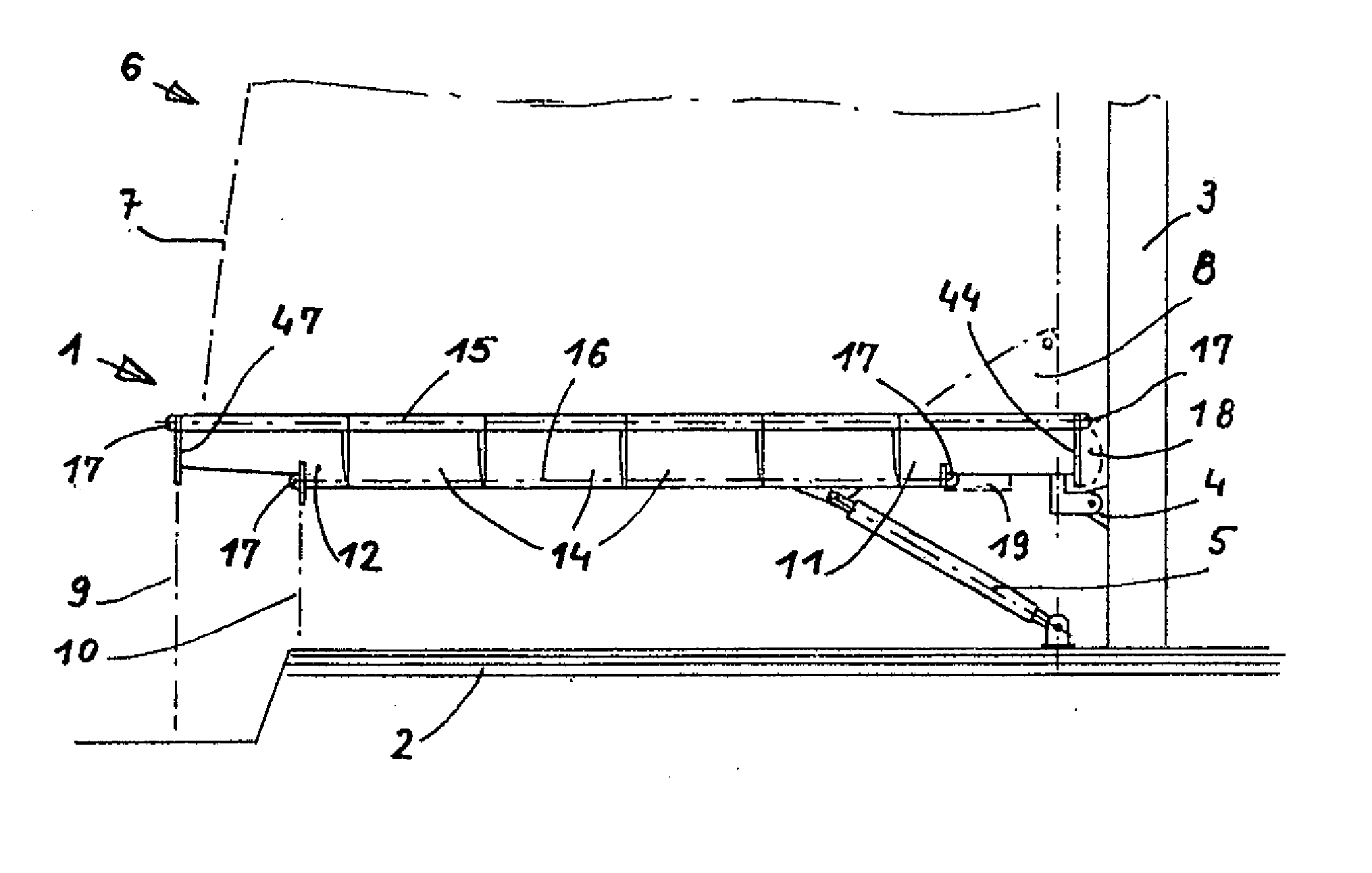
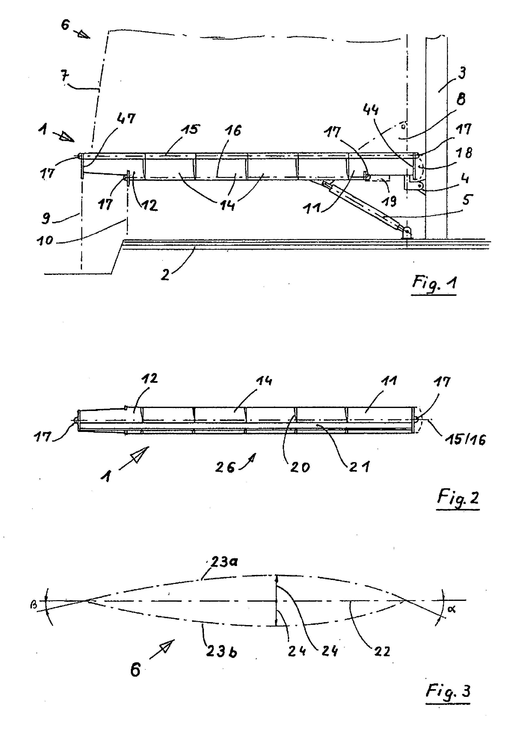
[0055]FIG. 1 is a side view of a roller reefing boom (1) according to the invention in a possible use position on a vessel (2) after a mast (3) to which it is connected by a gooseneck (4) so as to be deflectable on all sides and is held by a boom support (5) in a substantially horizontal position and at approx. 90° to the mast (3) in order to allow the sail (6) to be unrolled and rolled up.

[0056]Shown above the roller reefing boom (1) is an indicated sail (6) which has, when rolled out, an illustrated possible after leech position (7) and, when rolled in, a sail head (8). Also shown are a possible position of a mainsheet (9) and also a second (10) as an alternative, transferring the sail pull upward to the vessel. The roller reefing boom (1) comprises a plurality of partial segments: the head segment (11), the yardarm segment (12) and a plurality of similar center segments (14) therebetween all forming segment housings (26).

[0057]Illustrated by dot / dash lines is the central position...


PUM


Abstract

The invention relates to a roller reefing boom (1 in FIG. 1) for a boom sail set with sail battens, preferably a mainsail (6), of a ship (2) with a partially enclosing sail stowage space (27) of aluminium or Faserplast, in which a largely planar sail (6) can be reefed or stowed by rolling it up, wherein the trimming of the sail (6) in all reefing states is achieved by the roll reefing boom (1) comprising a number of segments (11, 12, 14) which can be swung away horizontally in relation to one another, making the sail (6) that is guided by them adjustable variably according to the strength of the wind by means of internal control devices (37 and 76) with fixed profile characteristics (23a and 23b) in the depth of the profile (24).

Description

[0001]The invention relates to a roller reefing boom comprising of a plurality of segments which are tiltable relative to one another in the horizontal plane and enclose a substantially circular fractional sail stowage space in the longitudinal direction.BACKGROUND OF THE INVENTION[0002]Conventional sail booms, in particular mainsail booms, are designed straight, the sail being either guided and held in a jag with the entire under leech or held with a free under leech only on the mast side and at the boom yardarm. In order to obtain a flow-advantageous profile adapted to the wind, use is made of sails which are shaped from a broad range of materials so as to bulge three-dimensionally and are stiffened with preferably horizontal, but also with vertical sail battens, which are shaped in a broad range of manners, in such a way as to allow the rear setting of the sail to be increased in size as much as possible and as a result a larger sail area and thus a larger area exposed to the win...

Claims


Application Information

Patent Timeline
IPC IPC(8): B63H9/10B63H9/04
CPCB63H9/1042B60W2555/60
Inventor WALDHAUSER, KURTWALDHAUSER, VOLKER
Owner WALDHAUSER KURT
Why Eureka
Try Eureka