
Buffer Underrun Handling

a buffer and underrun technology, applied in the field of graphical information processing, can solve the problem that the display controller is not yet available, and achieve the effect of reducing the visual effect of the underrun

Inactive Publication Date: 2011-07-14
APPLE INC
View PDF5 Cites 13 Cited by
  • Summary
  • Abstract
  • Description
  • Claims
  • Application Information

AI Technical Summary

Benefits of technology

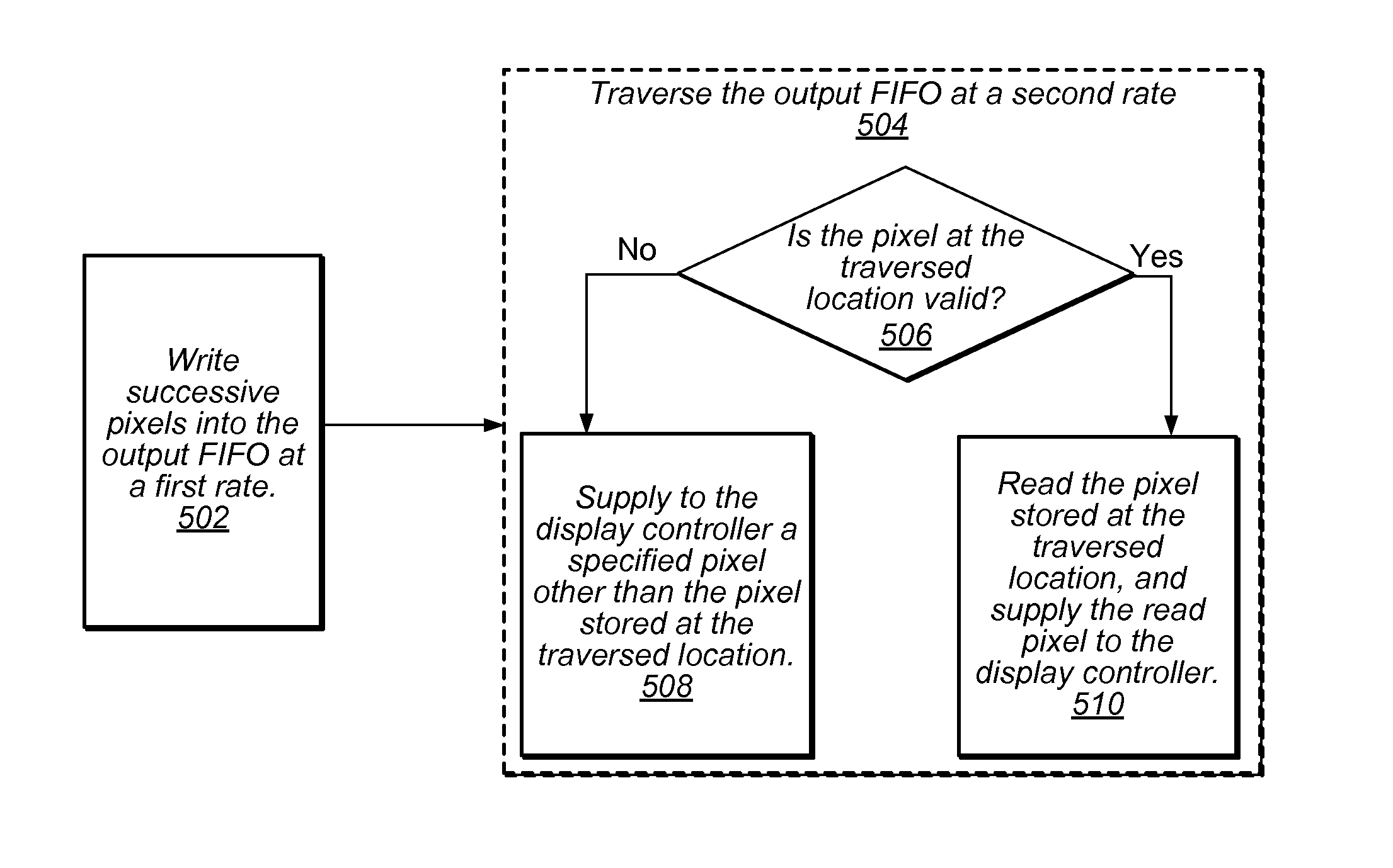
[0008]In one set of embodiments, the display pipe in a graphics system may feature an output buffer for storing pixels, which may be continuously read by a display controller for displaying on a display device. If the display controller pops pixels from the output buffer before those pixels are written by the display pipe, then a buffer underrun occurs. The output buffer may increment the read pointer for each underrun pop, so that when the display pipe catches up, the correct pixels will be displayed after the underrun is corrected. Various modes may be supported for the underrun pixels. A first mode may include outputting the most recent valid pixel, which may provide a “closest to correct” solution that may minimize the visual effect of the underrun. A second mode may include outputting a “stuck pixel” (which may be programmed) for the underrun pixels, which may be useful for debug as the underrun pixels may be visually obvious. A third mode may include outputting the stuck pixels for the rest of the current frame, even if the underrun is eventually corrected. A fourth mode may include outputting the stuck pixel for the rest of the frames, even if the underrun is eventually corrected.

Problems solved by technology

While under normal circumstances the image / video pixels are provided to the display controller at a sufficiently high rate to continuously display the current (expected) image / video frame, there may be cases when, for a variety of reasons, the pixels expected by the display controller are not yet available to the display controller.

Method used


Image

  • Buffer Underrun Handling
  • Buffer Underrun Handling
  • Buffer Underrun Handling

Examples


Embodiment Construction

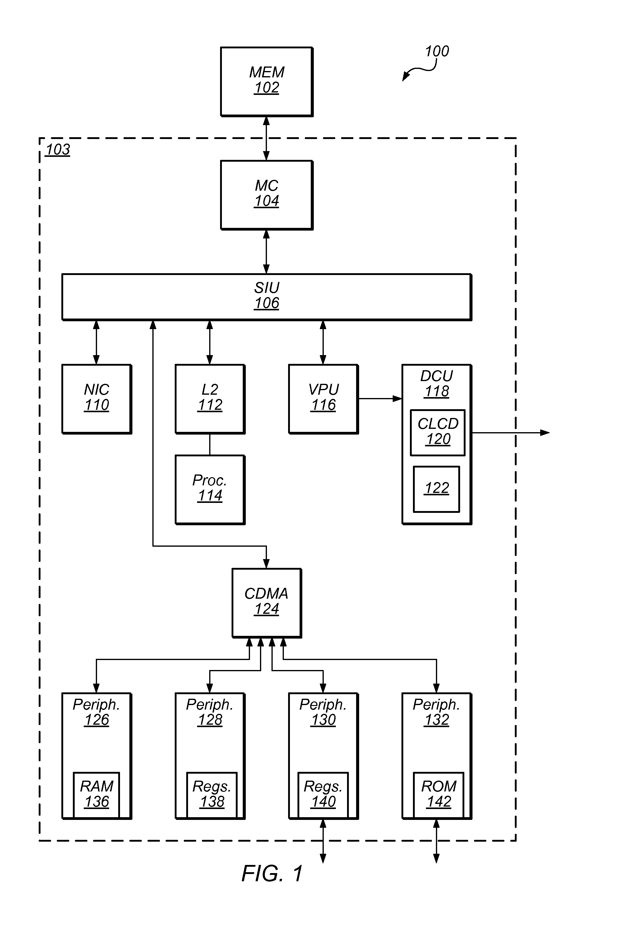
[0022]Turning now to FIG. 1, a block diagram of one embodiment of a system 100 that includes an integrated circuit 103 coupled to external memory 102 is shown. In the illustrated embodiment, integrated circuit 103 includes a memory controller 104, a system interface unit (SIU) 106, a set of peripheral components such as components 126-128, a central DMA (CDMA) controller 124, a network interface controller (NIC) 110, a processor 114 with a level 2 (L2) cache 112, and a video processing unit (VPU) 116 coupled to a display control unit (DCU) 118. One or more of the peripheral components may include memories, such as random access memory (RAM) 136 in peripheral component 126 and read-only memory (ROM) 142 in peripheral component 132. One or more peripheral components 126-132 may also include registers (e.g. registers 138 in peripheral component 128 and registers 140 in peripheral component 130 in FIG. 1). Memory controller 104 is coupled to a memory interface, which may couple to memor...


PUM


Abstract

A graphics system may include a display pipe with a buffer configured to store pixels to be processed by a display controller for displaying on a display device, with a buffer control circuit coupled to the buffer to supply pixels to the display controller. When the buffer control circuit detects an underrun of the buffer responsive to the display controller attempting to read pixels from the buffer that have not yet been written to the buffer, the buffer control circuit may supply an underrun pixel to the display. The underrun pixel may be selected from a set of previously stored set of underrun pixels, which may include a most recent valid pixel read by the display controller. A read pointer representative of the location in the buffer from where the display controller is currently attempting to read may be advanced even when an underrun condition occurs. The underrun pixel may be supplied to the display controller until the underrun has been resolved, at which point the most recent valid pixel read from the buffer may be supplied to the display controller.

Description

BACKGROUND[0001]1. Field of the Invention[0002]This invention is related to the field of graphical information processing, more particularly, to reading and writing registers that store image frame descriptors.[0003]2. Description of the Related Art[0004]Part of the operation of many computer systems, including portable digital devices such as mobile phones, notebook computers and the like is the use of some type of display device, such as a liquid crystal display (LCD), to display images, video information / streams, and data. Accordingly, these systems typically incorporate functionality for generating images and data, including video information, which are subsequently output to the display device. Such devices typically include video graphics circuitry to process images and video information for subsequent display.[0005]In digital imaging, the smallest item of information in an image is called a “picture element”, more generally referred to as a “pixel”. For convenience, pixels ar...

Claims


Application Information

Patent Timeline
IPC IPC(8): G09G5/36
CPCG06T1/60G09G5/39
Inventor BRATT, JOSEPH P.CHOO, SHINGHOLLAND, PETER F.MILLET, TIMOTHY J.TRIPATHI, BRIJESH
Owner APPLE INC
Learn More