Liquid ejection head and liquid ejection apparatus
a liquid ejection and liquid ejection technology, applied in printing and other directions, can solve the problems of piezoelectric layer, inability to eject liquid, so as to reduce the probability of occurrence of stress concentration at the boundary, reduce displacement characteristics, and reduce stress concentration
- Summary
- Abstract
- Description
- Claims
- Application Information
AI Technical Summary
Benefits of technology
Problems solved by technology
Method used
Image
Examples
first embodiment
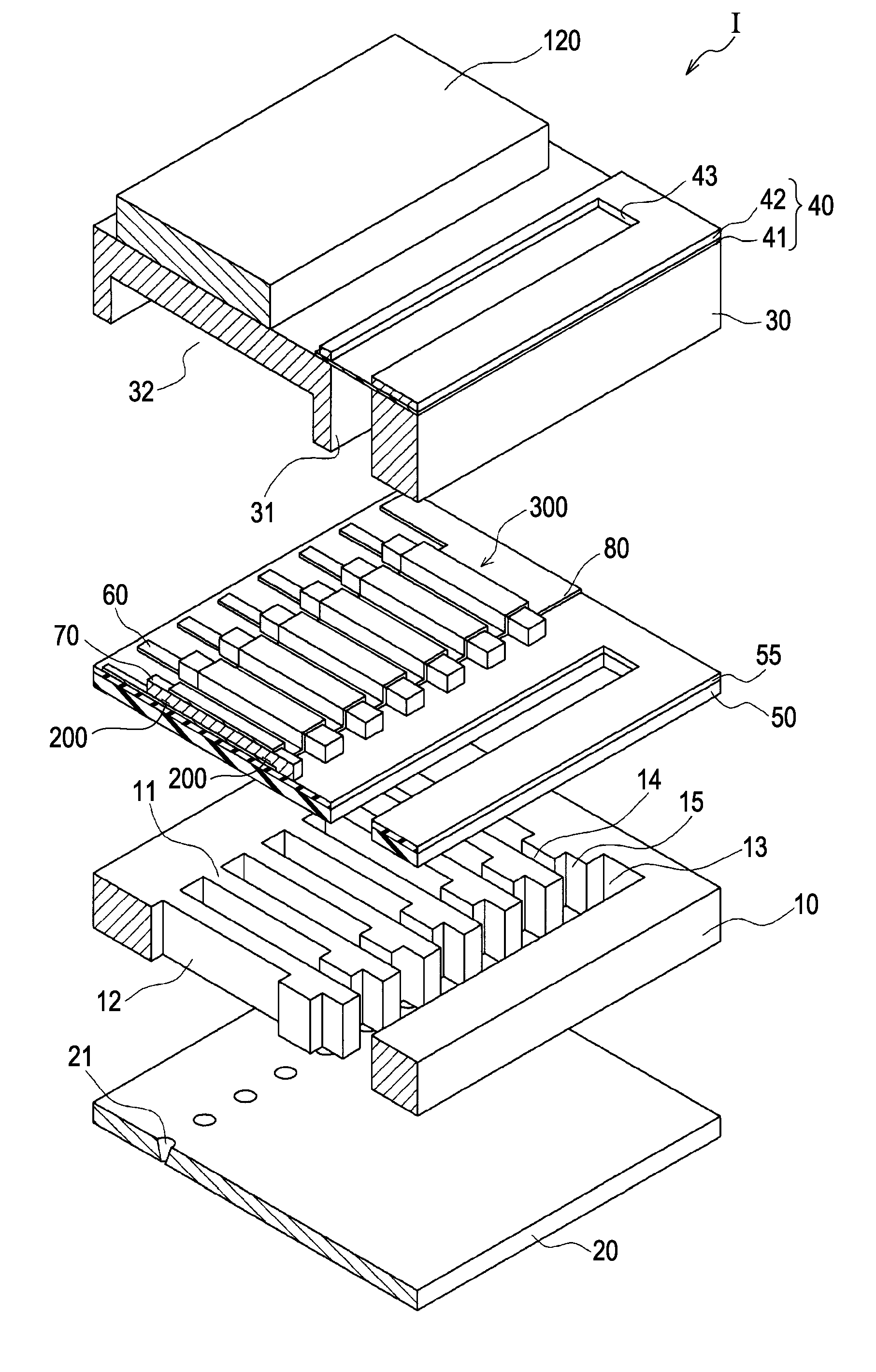
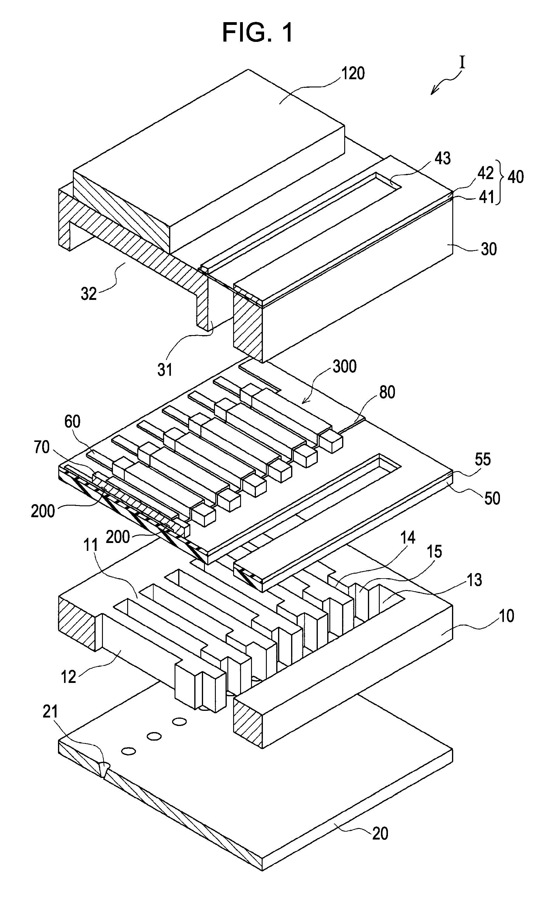
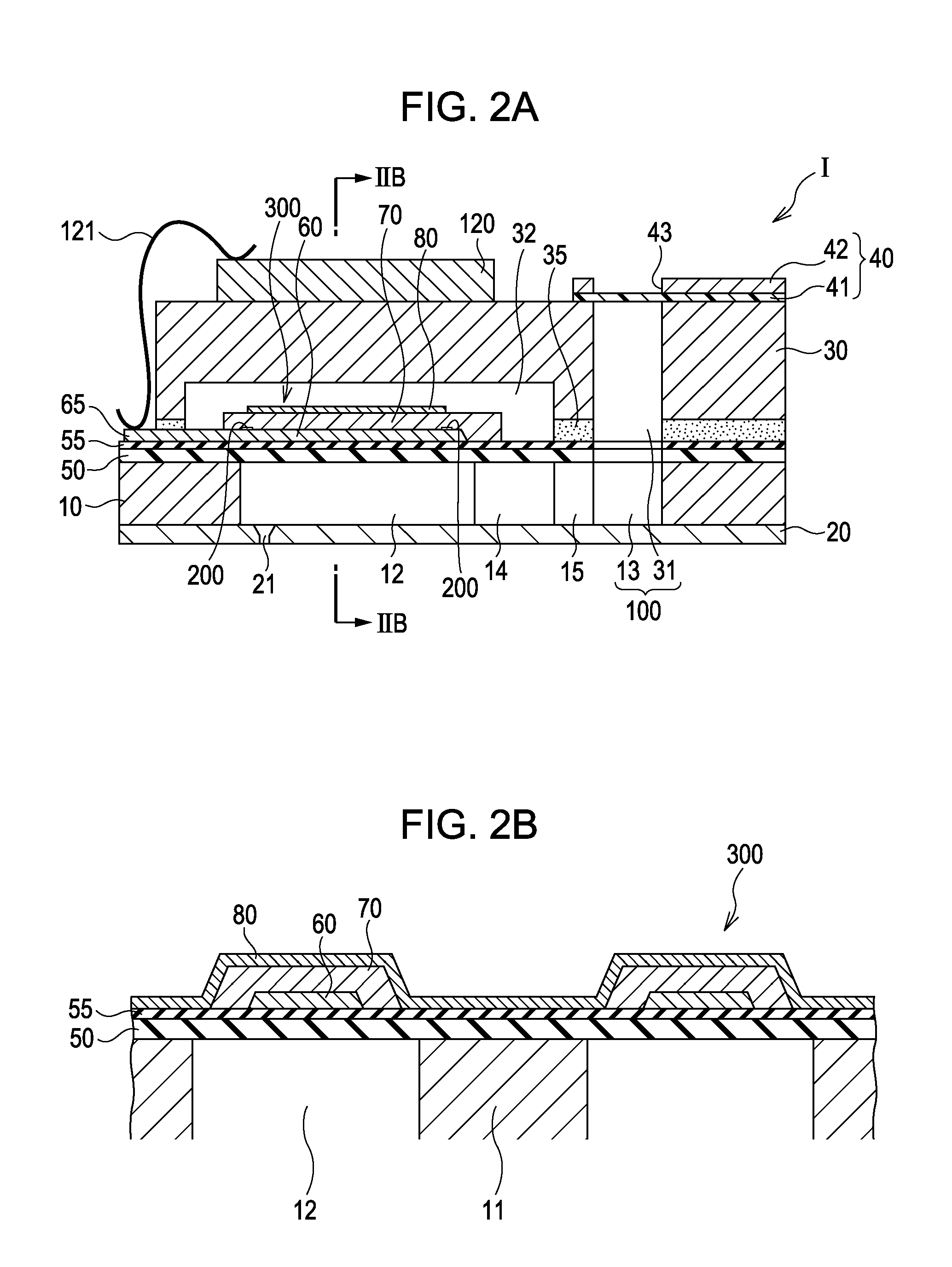
[0038]FIG. 1 is an exploded perspective view of an ink jet printhead as an example of a liquid ejection head according to a first embodiment of the invention. FIG. 2A is a cross-sectional view of the ink jet printhead, and FIG. 2B is an enlarged cross-sectional view taken along the line IIB-IIB in FIG. 2A.
[0039]As illustrated in the drawings, a flow-channel-containing substrate 10 in this embodiment is formed of a silicon monocrystal substrate, and is formed with a resilient film 50 formed of silicon dioxide on one of the surfaces thereof.
[0040]The flow-channel-containing substrate 10 is formed with a plurality of pressure generating chambers 12 arranged in a line in the direction of width thereof. The flow-channel-containing substrate 10 is formed with a communicating portion 13 in an area lengthwise outside of the pressure generating chambers 12, and the communicating portion 13 and the respective pressure generating chambers 12 are communicated via ink supply channels 14 and comm...
second embodiment
[0097]FIG. 10 is an enlarged plan view of an principal portion of an ink jet printhead as an example of the liquid ejection head according to a second embodiment of the invention. The like elements are designated by the same numerals as in the first embodiment and overlapped description will be omitted.
[0098]As shown in FIG. 10, a piezoelectric element 300A in the second embodiment includes the first electrode 60, a low dielectric material layer 200A, the piezoelectric layer 70, and the second electrode 80.
[0099]The low dielectric material layer 200A is disposed continuously across the boundary A between the active portion 320 and the non-active portion 330 at the boundary A between the active portion 320 and the non-active portion 330 on the side of the ink supply channel 14 in the longitudinal direction of the pressure generating chamber 12 (the direction intersecting the direction of arrangement of the pressure generating chambers 12).
[0100]The low dielectric material layer 200A ...
third embodiment
[0110]FIG. 12 is an enlarged plan view of an principal portion of an ink jet printhead as an example of the liquid ejection head according to a third embodiment of the invention. The like elements are designated by the same numerals as in the first embodiment and overlapped description will be omitted.
[0111]As shown in FIG. 12, a piezoelectric element 300B in the third embodiment includes the first electrode 60, a low dielectric material layer 200B, the piezoelectric layer 70, and the second electrode 80.
[0112]The low dielectric material layer 200B includes a plurality of long-strip-shaped first low dielectric portions 202 disposed continuously across the boundary A between the active portion 320 and the non-active portion 330 at the boundary A between the active portion 320 and the non-active portion 330 on the side of the ink supply channel 14 in the longitudinal direction of the pressure generating chamber 12 (the direction intersecting the direction of arrangement of the pressur...
PUM
 Abstract
Description
Claims
Application Information
 - R&D
- Intellectual Property
- Life Sciences
- Materials
- Tech Scout
- Unparalleled Data Quality
- Higher Quality Content
- 60% Fewer Hallucinations
Browse by: Latest US Patents, China's latest patents, Technical Efficacy Thesaurus, Application Domain, Technology Topic, Popular Technical Reports.
© 2025 PatSnap. All rights reserved.Legal|Privacy policy|Modern Slavery Act Transparency Statement|Sitemap|About US| Contact US: help@patsnap.com


