Image capturing lens, optical apparatus having same, and method for manufacturing image-capturing lens

a technology of image capture and optical apparatus, which is applied in the direction of manufacturing tools, instruments, television systems, etc., can solve the problems of image quality drop, image blur, and difficulty for users to hold the camera, and achieve excellent optical performance and minimal performance change

Inactive Publication Date: 2011-07-14
NIKON CORP
View PDF15 Cites 31 Cited by
  • Summary
  • Abstract
  • Description
  • Claims
  • Application Information

AI Technical Summary

Benefits of technology

[0026]According to this present invention, an image-capturing lens which can correct various aberrations well, can minimize the performance change upon shifting the lens, is compact, and has excellent optical performance throughout the entire screen, an optical apparatus having this image-capturing lens, and a method for manufacturing this image-capturing lens can be provided.

Problems solved by technology

Conventional lenses, however, are not sufficiently downsized, and when such a lens is used in a camera, it is difficult for a user to hold the camera, and image blur occurs and image quality drops during exposure, because of the subtle blur of the camera generated when capturing an image (e.g. blur of camera generated when the user presses a release button).

Method used


Image

  • Image capturing lens, optical apparatus having same, and method for manufacturing image-capturing lens
  • Image capturing lens, optical apparatus having same, and method for manufacturing image-capturing lens
  • Image capturing lens, optical apparatus having same, and method for manufacturing image-capturing lens

Examples


example 1

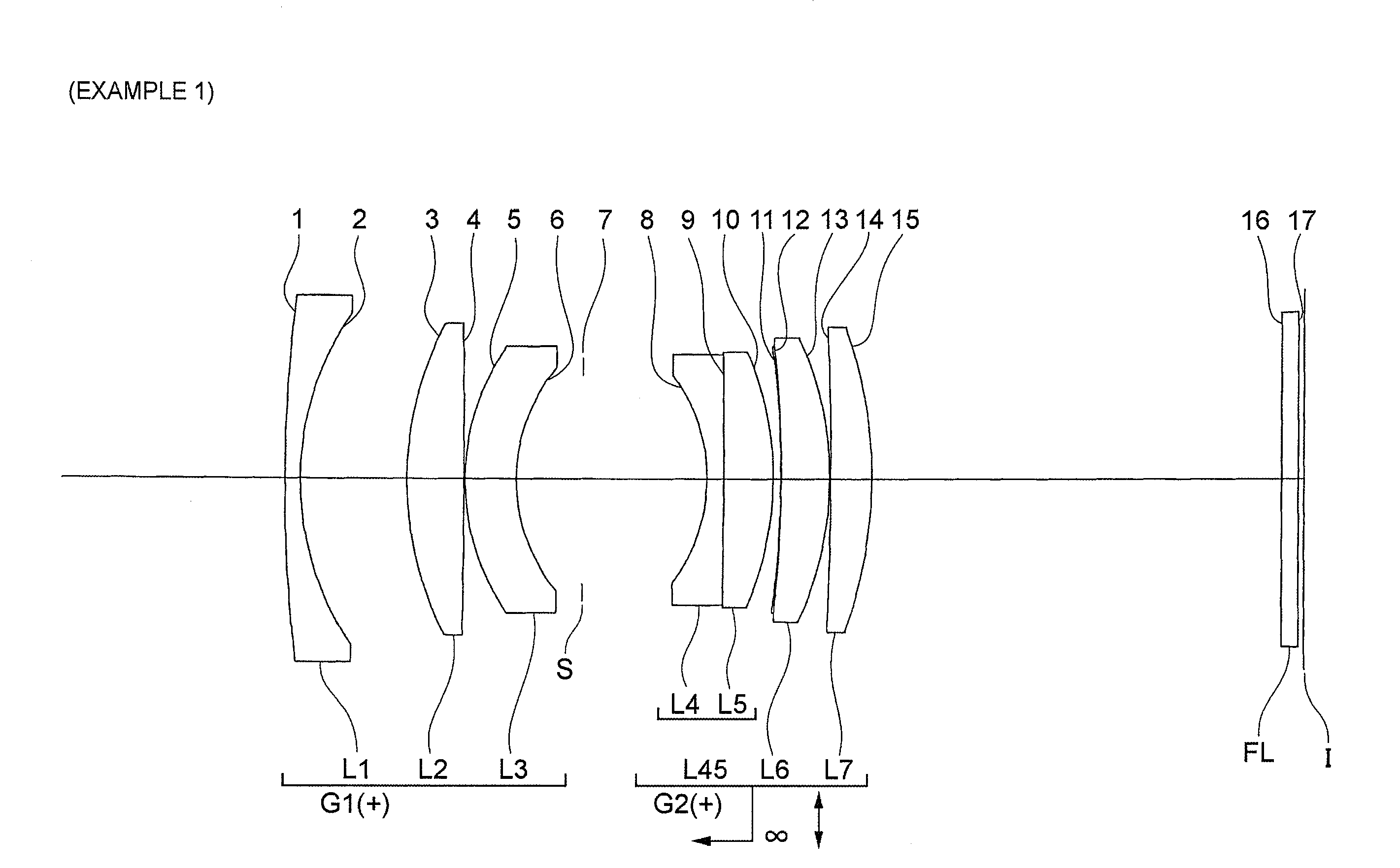
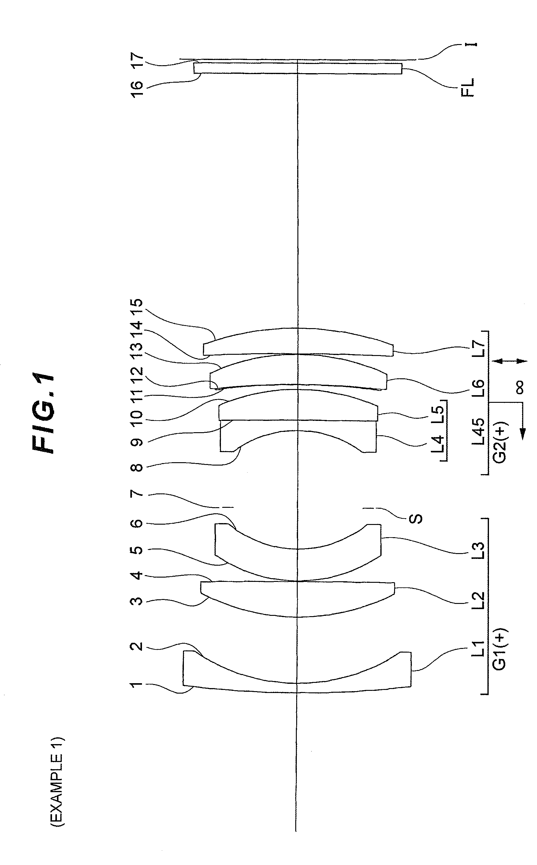
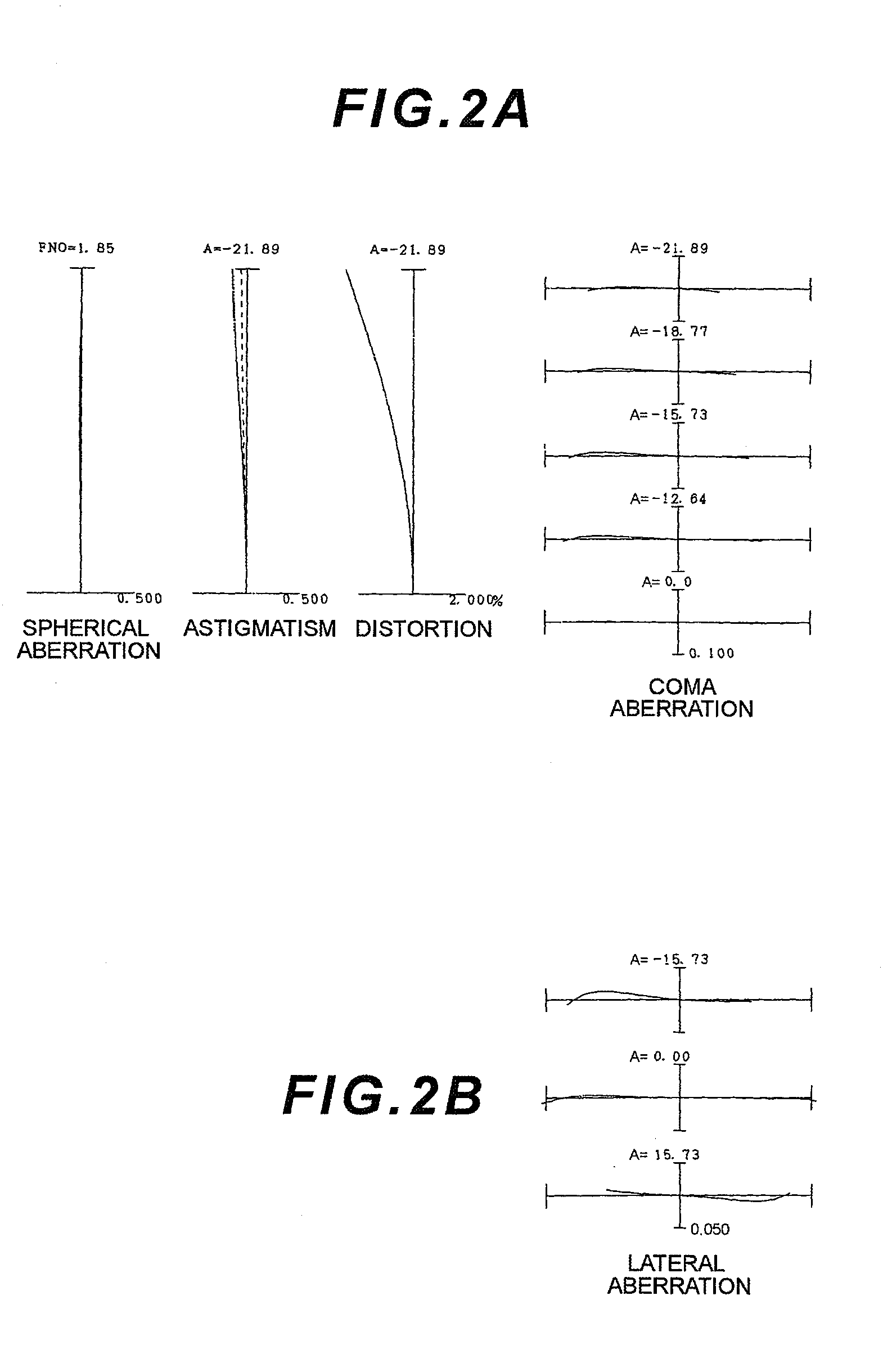
[0090]Example 1 will be described with reference to FIG. 1 to FIG. 3 and Table 1. FIG. 1 is a diagram depicting a configuration of an image-capturing lens according to Example 1, and a moving state of each lens upon a focusing state changing from focusing on infinity to focusing on a close distance. In this example, “close distance” means a −0.025× image-capturing distance.

[0091]As FIG. 1 shows, the image-capturing lens according to Example 1 has, in order from an object, an object side lens group G1 having positive refractive power, an image side lens group G2 having positive refractive power, and a filter group FL constituted by a low pass filter, infrared cut filter, or the like. Upon a focusing state Changing from focusing on infinity to focusing on close distance, that is upon focusing, the object side lens group G1 is fixed with respect to the image plane I and the image side lens group G2 moves with respect to the image plane I, and the distance between the object side lens g...

example 2

[0099]Example 2 will be described with reference to FIG. 4 to FIG. 6 and Table 2. FIG. 4 is a diagram depicting a configuration of an image-capturing lens according to Example 2, and a moving state of each lens upon a focusing state changing from focusing on infinity to focusing on a close distance. In this example, “close distance” means a −0.020× image-capturing distance.

[0100]As FIG. 4 shows, the image-capturing lens according to Example 2 has, in order from an object, an object side lens group G1 having positive refractive power, an image side lens group G2 having positive refractive power, and a filter group FL constituted by a low pass filter, infrared cut filter, or the like. Upon a focusing state changing from focusing on infinity to focusing on close distance, that is upon focusing, the object side lens group G1 is fixed with respect to the image plane I and the image side lens group G2 moves with respect to the image plane I, and the distance between the object side lens g...

example 3

[0107]Example 3 will be described with reference to FIG. 7 to FIG. 9 and Table 3. FIG. 7 is a diagram depicting a configuration of an image-capturing lens according to Example 3, and a moving state of each lens upon a focusing state changing from focusing on infinity to focusing on a close distance. In this example, “close distance” means a −0.025× image-capturing distance.

[0108]As FIG. 7 shows, the image-capturing lens according to Example 3 has, in order from an object, an object side lens group G1 having positive refractive power, an image side lens group G2 having positive refractive power, and a filter group FL constituted by a low pass filter, infrared cut filter, or the like. Upon a focusing state changing from focusing on infinity to focusing on close distance, that is upon focusing, the object side lens group G1 is fixed with respect to the image plane I and the image side lens group G2 moves with respect to the image plane I, and the distance between the object side lens g...


PUM

PropertyMeasurementUnit
wavelengthaaaaaaaaaa
refractive poweraaaaaaaaaa
focal lengthaaaaaaaaaa

Abstract

An image-capturing lens has, in order from an object, an object side lens group G1 and an image side lens group G2 which is disposed next to the object side lens group G1 with an air space, and focusing is performed from a distant object to a close object by moving at least a part of the image side lens group G2 along an optical axis as a focusing lens group, and image stabilization is performed by moving at least a part of the image side lens group G2 as a shift lens group so as to have components roughly orthogonal to the optical axis.

Description

TECHNICAL FIELD[0001]The present invention relates to an image-capturing lens, an optical apparatus having this image-capturing lens, and a method for manufacturing the image-capturing lens.TECHNICAL BACKGROUND[0002]As a large aperture standard lens used for a photograph camera and video camera, many Gauss lenses, in which refractive power is substantially symmetric with respect to an aperture stop provided between the lenses, have been proposed (e.g. see Patent Document 1).[0003]Conventional lenses, however, are not sufficiently downsized, and when such a lens is used in a camera, it is difficult for a user to hold the camera, and image blur occurs and image quality drops during exposure, because of the subtle blur of the camera generated when capturing an image (e.g. blur of camera generated when the user presses a release button).[0004]A known method to solve this problem is combining a detection system for detecting camera blur, a computing system for controlling the shift lens ...

Claims


Application Information

Patent Timeline
Patent Type & Authority Applications(United States)
IPC IPC(8): H04N5/225B23P17/04
CPCG02B13/00Y10T29/49826G03B43/00G02B27/646
Inventor TAKE, TOSHINORISENSUI, TAKAYUKI
Owner NIKON CORP
Why Eureka
Try Eureka