
Additional stabilization device for endo-osseous dental implant

a dental implant and stabilization device technology, applied in dental implants, dental surgery, medical science, etc., can solve the problems of not being able to make teeth, not always allowing proper stabilization of implants on bone level, and not being able to provide anti-rotational means to the anchoring foo

Active Publication Date: 2011-07-14
SADDLE IMPLANT TECH SARL
View PDF9 Cites 12 Cited by
  • Summary
  • Abstract
  • Description
  • Claims
  • Application Information

AI Technical Summary

Benefits of technology

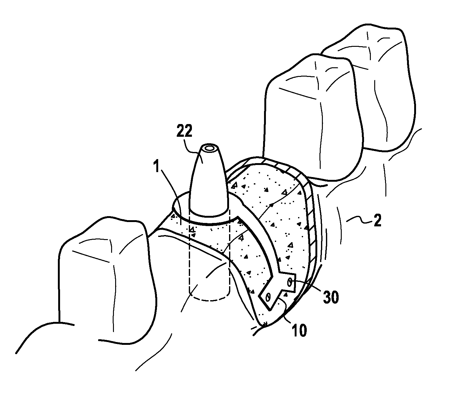
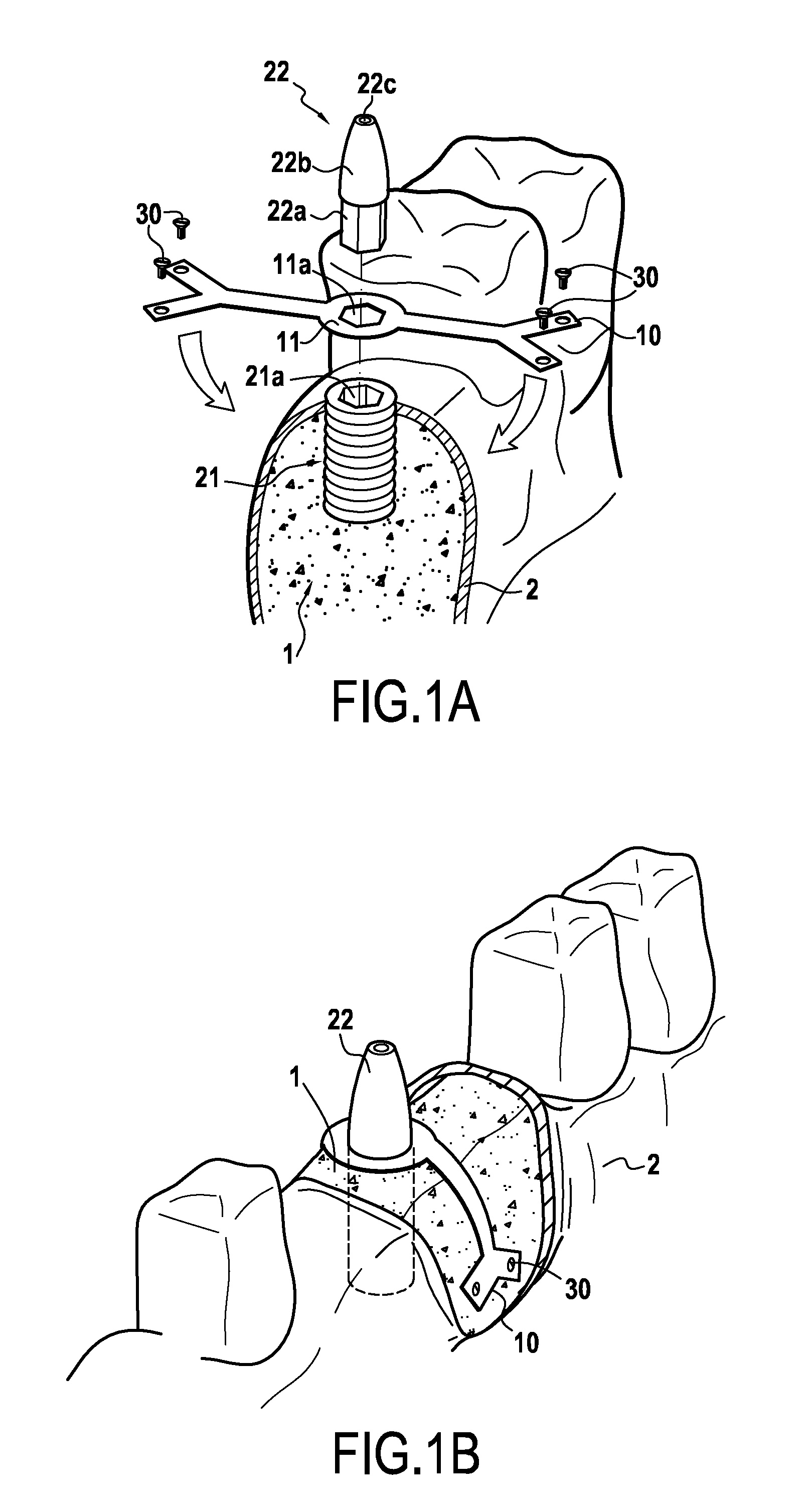
"The present invention proposes an additional stabilization device for an endo-osseous dental implant that can be used in combination with the implant. The device comprises a central platform with a perforation that allows for the introduction of the implant's pillar through the platform, and flexible side slender anchoring extensions that can be placed straddling the bone of the jaw. The device is designed to inhibit rotational movements of the pillar once it is placed in the anchoring foot, and can be used in a temporary or permanent manner. It allows for stable installation of the implant without the need for additional steps and can be easily installed and de- installed from the mouth of the patient."

Problems solved by technology

Therefore, except in cases when the bone has very favorable density and amount, it is not possible to make the tooth during this period of time between three and six months.
Further, with this method, the results obtained on the bone level do not always allow proper stabilization of the implant.
In known devices, there is no intention of providing the anchoring foot with anti-rotational means.
This solution nevertheless has the disadvantage of having to systematically install the plate / foot / pillar assembly and of not being able to modulate this installation.
In spite of the development of implant technology, it happens that endo-osseous implants continue to have mobility at the end of the healing period and are therefore subject to a lack of osteo-integration.

Method used


Image

  • Additional stabilization device for endo-osseous dental implant
  • Additional stabilization device for endo-osseous dental implant
  • Additional stabilization device for endo-osseous dental implant

Examples


first embodiment

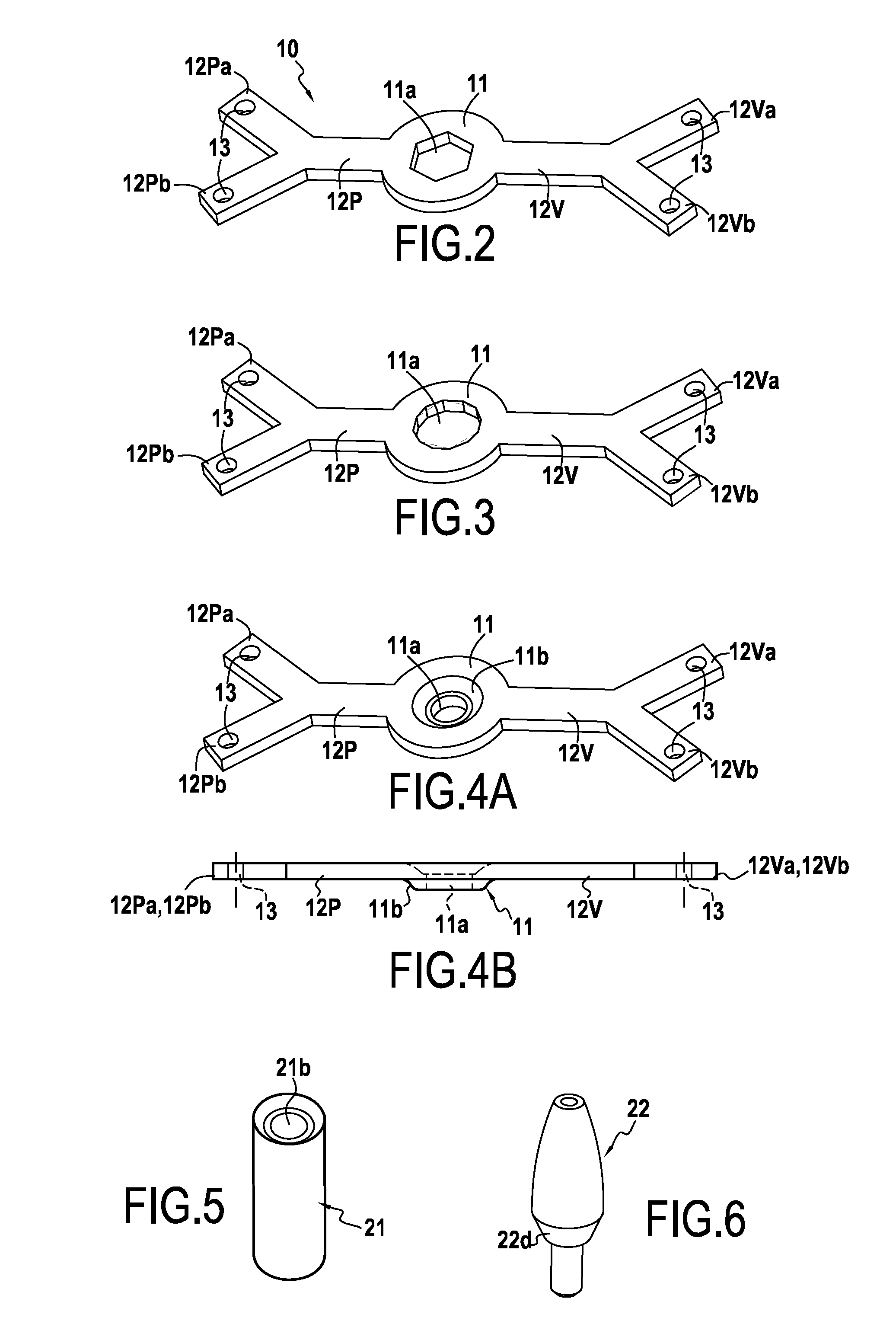
[0078]FIG. 2 shows a first application of a first embodiment according to the invention, wherein the perforation 11a of the central platform 11 has a hexagonal shape. The central portion 11 has two side extensions as arms 12P and 12V which each assume the shape of a Y and therefore comprise at their ends, two branches, 12Va, 12Vb and 12Pa, 12Pb, respectively. It is noted in this figure that the arm 12V is longer than the arm 12P. This meets an anatomic need. Indeed, it is desirable that the side extension 12V intended to be fixed on the vestibular side be longer than the side extension 12P intended to be fixed on the palatine side.

[0079]FIG. 3 illustrates a second application of the first embodiment according to the invention, wherein the perforation 11a comprises twelve sides and therefore has a dodecagonal regular polygon shape. This application gives the possibility of placing the hexagon of the pillar 22 illustrated in FIG. 1 inside the perforation 11a in six different angular p...

second embodiment

[0081]FIG. 4 shows a stabilization device according to an application of a This stabilization device 10 is intended to operate by cooperating with an implant comprising an anchoring foot of the type of the one illustrated in FIG. 5 and an external pillar of the type of the one illustrated in FIG. 6. In this embodiment, anti-rotational frictional means are used between the external foot 22 of FIG. 6 and the anchoring foot 21 of FIG. 5 in order to inhibit their relative movements. Such anti-rotational frictional means are generally formed by a portion 22d of the base of the pillar 22 having a conical shape and intended to bear upon a matching also conical shape 21b of the anchoring foot 21. When the external pillar 22 is placed in the anchoring foot and fixed by screwing a screw introduced into the orifice 22c, the presence of the conical surfaces rubbing against each other gives the possibility of avoiding relative rotation of the pillar 22 relatively to the anchoring foot 21. Here ...


PUM


Abstract

An additional stabilization device intended to be used in combination with an endo-osseous dental implant, such an endo-osseous implant which has at least one endo-osseous anchoring foot adapted to an installation in a jaw bone of a patient so as to cooperate with an external pillar intended to be fixed into the anchoring foot and further has means for fixing a dental prosthetic element, the anchoring foot and the pillar further has anti-rotational means with which the relative movements of the pillar relatively to the anchoring foot may be inhibited, once the pillar is placed in the anchoring foot.

Description

BACKGROUND OF THE INVENTION[0001]The present invention relates to the general field of dental implants.[0002]More particularly, the invention relates to endo-osseous dental implants and more specifically to the stabilization of these implants.[0003]Presently, endo-osseous implants are conventionally based on the use of an anchoring foot, for example an anchoring screw, adapted so as to be installed in a jaw bone of a patient. This anchoring foot cooperates with an external pillar intended to be fixed in the anchoring foot. The external pillar therefore comprises means for being fixed in the anchoring foot and means for fixing a dental prosthetic element which will cap the external pillar and protrude above the jaw bone of the patient in order to replace the missing dental element. The prosthetic outer pillar is stabilized relatively to the anchoring foot with anti-rotational means with which relative movements of the pillar relatively to this anchoring foot are inhibited.[0004]Furth...

Claims


Application Information

Patent Timeline
Patent Type & Authority Applications(United States)
IPC IPC(8): A61C8/00
CPCA61C8/0031A61C8/0009
Inventor DACREMONT, PHILIPPE
Owner SADDLE IMPLANT TECH SARL
Learn More