

Shaped heterogeneous catalysts
a heterogeneous catalyst and shape technology, applied in the direction of catalyst activation/preparation, metal/metal-oxide/metal-hydroxide catalyst, chemical production, etc., can solve the problem that the strength and geometric surface area may not always be sufficient for the most demanding uses
Active Publication Date: 2011-07-14
JOHNSON MATTHEY PLC
View PDF18 Cites 9 Cited by
- Summary
- Abstract
- Description
- Claims
- Application Information
AI Technical Summary
Benefits of technology
[0005]Whereas both flutes and holes may increase the theoretical geometric surface area (GSA), the strength of the pellets generally is reduced with increasing number of holes and flutes. Historically, although 4-, 7- and 10-holed pellets are produced, the strength and geometric surface area may still not always be sufficient for the most demanding uses. We have designed catalyst units that overcome the problems associated with such designs.
Problems solved by technology
Historically, although 4-, 7- and 10-holed pellets are produced, the strength and geometric surface area may still not always be sufficient for the most demanding uses.
Method used
View moreImage
Smart ImageViewing Examples

Examples
example 1
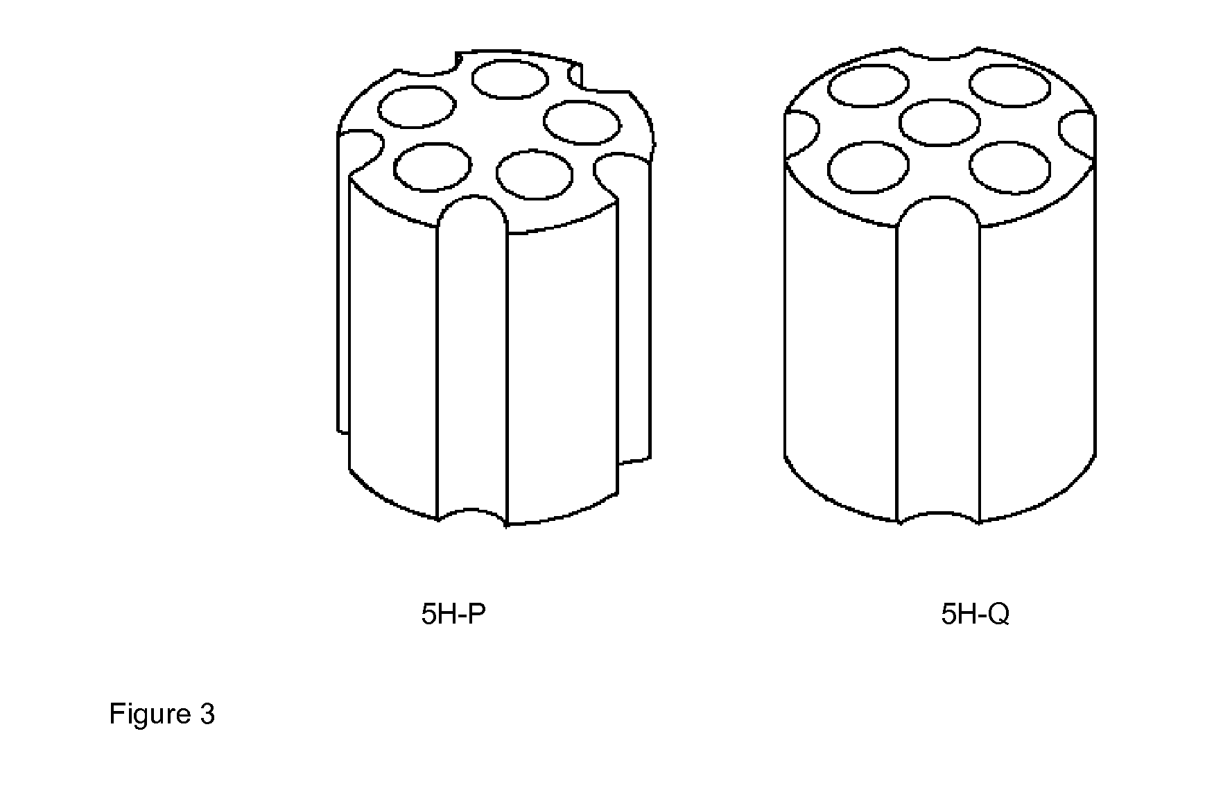
[0042]Based on a computational study on the pellets depicted in FIG. 3, the calculated properties of 5H-P (according to the invention) and 5H-Q (not according to the invention), fabricated from the same material are given below.
5H-Q5H-PPropertiesA mm1.01.0B mm1.01.0C mm18.018.0D mm16.016.0Flute width / depth mm4.0 / 4.03.5 / 2.5Hole diameter (d′) mm4.03.8ResultsGeometric Surface area (m2 / m3)368.2379.3Voidage109.1109.2Equivalent Diameter (mm)5.245.18Strength130154
[0043]The geometric surface area (GSA) is marginally superior but the strength is markedly improved in the design according to the present invention.
Login to View More PUM
| Property | Measurement | Unit |
|---|---|---|
| Fraction | aaaaa | aaaaa |
| Electric dipole moment | aaaaa | aaaaa |
| Electric dipole moment | aaaaa | aaaaa |
Abstract
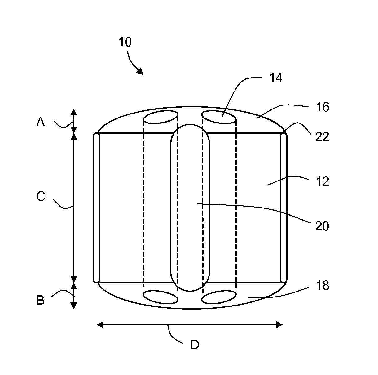
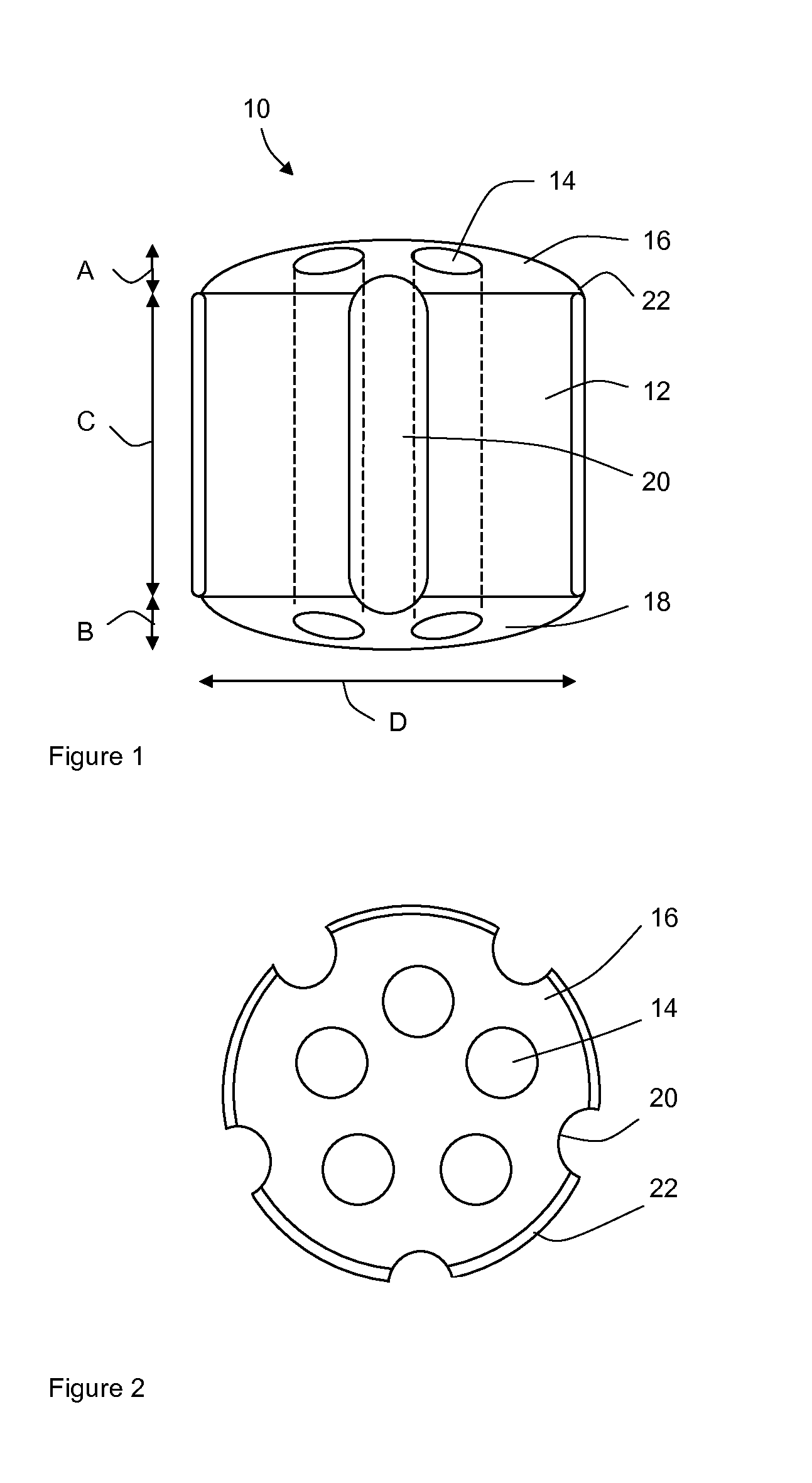
A catalyst unit is described comprising a cylinder with a length C and a diameter D, wherein said unit has five holes arranged in a pentagonal pattern extending longitudinally therethrough, with five flutes running along the length of the unit, said flutes positioned equidistant adjacent holes of said pentagonal pattern. The catalyst may be used particularly in steam reforming reactors.
Description
CROSS-REFERENCE TO RELATED APPLICATIONS[0001]This application is the U.S. National Phase application of PCT International Application No. PCT / GB2009 / 051052, filed Aug. 24, 2009, and claims priority of British Patent Application No. 0816705.8, filed Sep. 12, 2008, the disclosures of both of which are incorporated herein by reference in their entirety for all purposes.FIELD OF THE INVENTION[0002]This invention relates to shaped heterogeneous catalysts.BACKGROUND OF THE INVENTION[0003]Heterogeneous catalysts are typically provided as particulate beds through which a liquid and / or gaseous reactant mixture is passed, often at elevated temperature and pressure. Therefore heterogeneous catalytic materials are often provided in shaped form to provide a balance of catalytic activity and throughput. In general, smaller catalyst particles have a higher surface area, and therefore activity, but provide lower throughput because the pressure drop through the catalyst bed is higher. To counter thi...
Claims
Login to View More Application Information
Patent Timeline
 IPC IPC(8): B01J27/232B01D53/64C01C1/02B01J35/02B01J27/236B01J21/06B01J23/00B01J23/30B01J23/26B01J23/28B01J23/34B01J23/75B01J23/755B01J23/745B01J23/44B01J23/02B01J23/06B01J23/04B01J23/72B01J23/50B01J23/14B01J23/22B01J21/02B01J32/00C07C27/00C07C29/00B01J21/10B01J23/10B01J23/20B01J23/46B01J23/18B01J23/36B01J23/42B01J23/52B01J21/04B01J37/00B01J37/02B01J37/08
CPCB01J23/40C01B2203/1005B01J23/755B01J35/002B01J35/023B01J35/026B01J37/0009B01J37/0201C01B3/16C01B3/40C01B2203/0233C01B2203/0244C01B2203/0261C01B2203/0283B01J23/70Y02P20/52B01J35/50B01J35/30B01J35/40B01J23/00B01J37/02C07C1/00B01J35/00
InventorBIRDSALL, DAVID JAMESBABOVIC, MILETACARLSSON, MIKAEL PER UNOFRENCH, SAMUEL ARTHURNIJEMEISLAND, MICHIELSENGELOW, WILLIAM MAURICESTITT, EDMUND HUGH
OwnerJOHNSON MATTHEY PLC