
Honeycomb structure

一种蜂窝结构体、蜂窝结构的技术,应用在催化剂载体、家里用具、发动机元件等方向,能够解决劣化、无法抑制流量净化性能、废气流易发生停滞等问题,达到净化性能提高的效果

Active Publication Date: 2018-10-23
NGK INSULATORS LTD
View PDF7 Cites 0 Cited by
  • Summary
  • Abstract
  • Description
  • Claims
  • Application Information

AI Technical Summary

Problems solved by technology

However, if the same number of fins are evenly arranged on each side like the honeycomb structure of Patent Document 1, there is a problem that the exhaust gas flow is extremely prone to stagnation, and the purification at a high flow rate (high flow rate) cannot be suppressed. performance degradation

Method used


Image

  • Honeycomb structure
  • Honeycomb structure
  • Honeycomb structure

Examples


Embodiment 1

[0095] In Example 1, first, a molding material for producing a honeycomb structure was prepared. Specifically, a binder, a surfactant, a pore-forming material, and water are added to a ceramic raw material to form a molding raw material. It should be noted that kaolin, talc, and alumina, which are cordierite-forming raw materials, were used as ceramic raw materials.

[0096] Next, the obtained molding raw materials are kneaded with a kneader, and then kneaded with a vacuum mud mill to form a green body. Next, the obtained green body is extruded using a nozzle to produce a honeycomb molded body. As the nozzle, a nozzle for forming a honeycomb formed body having unevenly provided protrusions (that is, uneven corners) was used. After the honeycomb molded body is fired, the thickness of the partition wall is 0.089mm, and the cell density is 62 cells / cm 2 . The shape of the cells of the formed honeycomb body (the shape of the cells in a cross section perpendicular to the direct...

Embodiment 2~14、 comparative example 1、2

[0135] A honeycomb structure was produced in the same manner as in Example 1 except that the protrusions were arranged as shown in Table 1 and Table 2.

[0136] For the honeycomb structures of Examples 2 to 14 and Comparative Examples 1 and 2, the thickness of the partition wall (mm), the porosity (%) of the partition wall, and the cell density (cells / cm2) were measured in the same manner as in Example 1. 2 ), carry out LA-4 test and pressure loss measurement. The results are shown in Tables 1 to 3.

[0137] (result)

[0138] As shown in Table 3, it can be seen that the honeycomb structures of Examples 1 to 14 have uneven arrangement of protrusions, and thus, compared with the honeycomb structures of Comparative Examples 1 and 2, the exhaust gas purification performance after catalyst loading higher.


PUM


Abstract

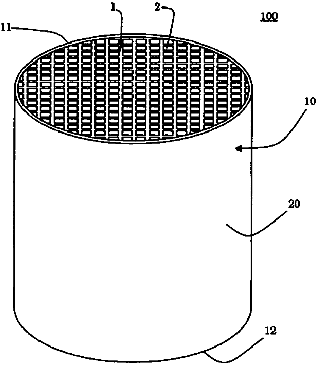
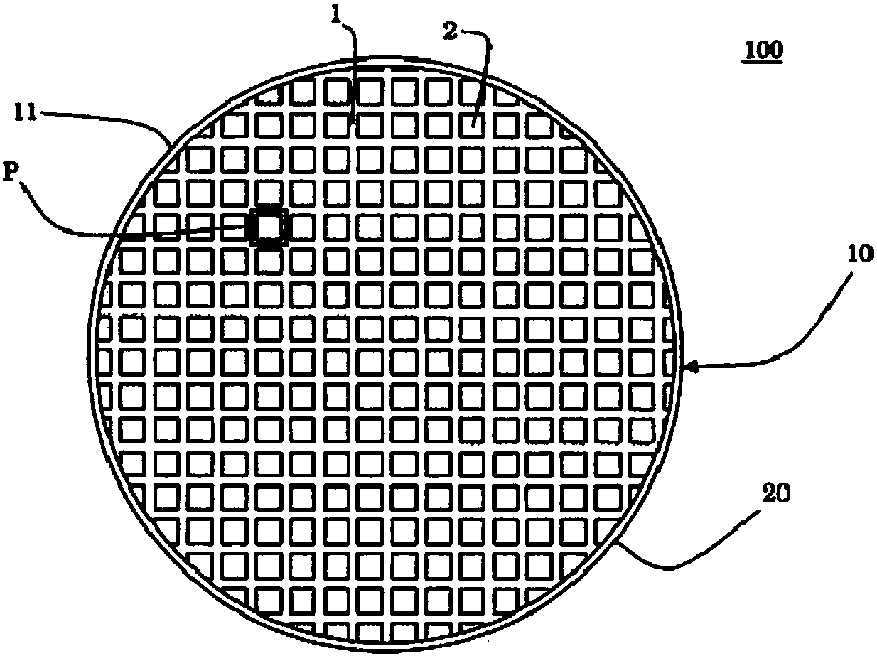
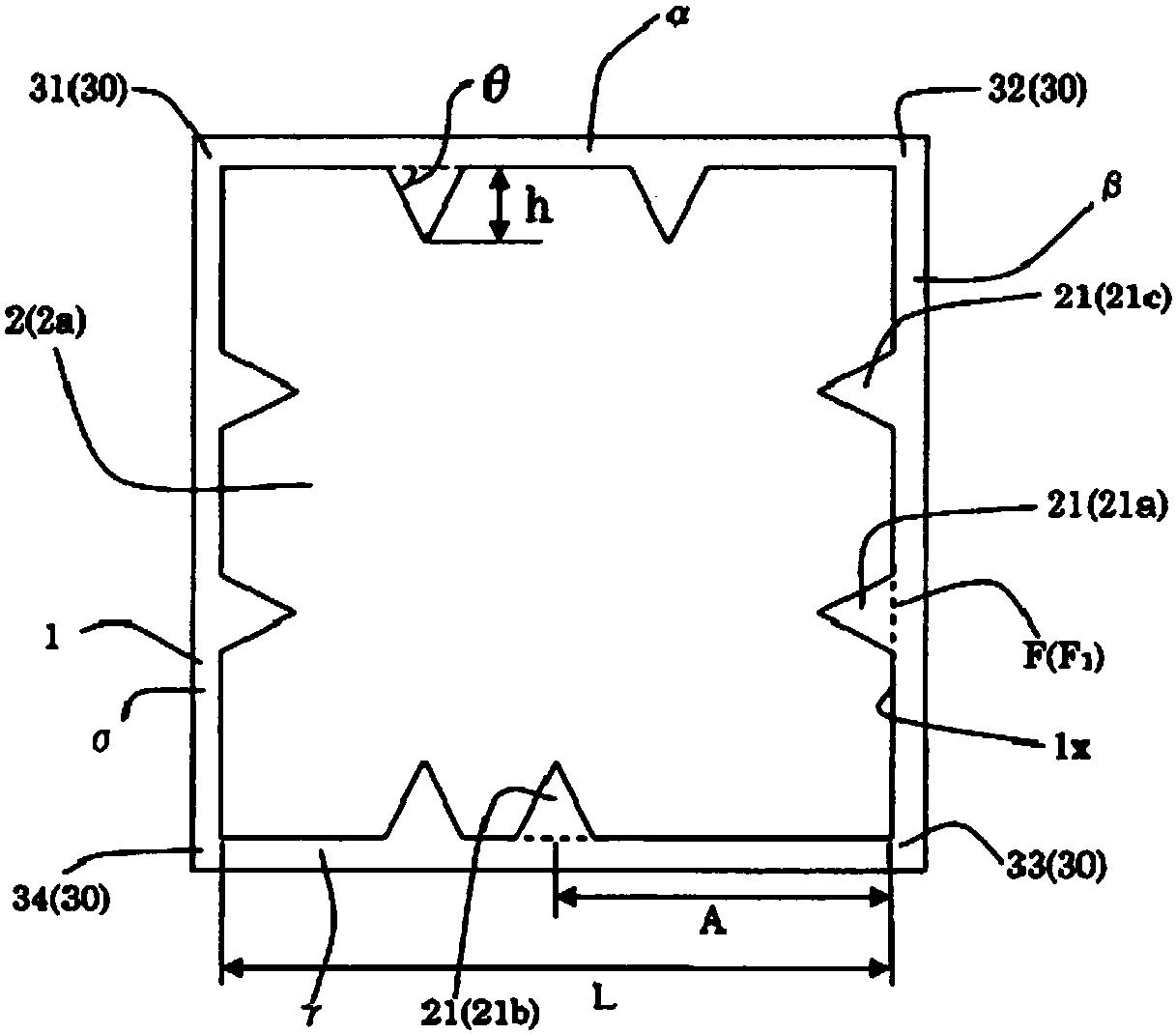
The present invention provides a honeycomb structure including a honeycomb structure portion having a partition wall partitioning a compartment; a compartment is provided with protrusions on both sides extending from a corner of the compartment; a protrusion disposed at a shorter distance from the one corner portion to the protrusion portion from a corner extending from a corner portion and located at a position closest to the corner portion as a first protrusion portion; a protrusion disposed at a longer distance from the one corner portion to the protrusion portion from a corner extending from a corner portion and located at a position closest to the corner portion as a second protrusion portion; the length of one side on which the second protrusion is provided is L, the distance from the corner portion to the bottom center position of the second protrusion is A, and the number of protrusions on the side on which the second protrusion is provided is N,the relationship of the formula(1): 1 / (N+1) < A / L is satisfied. The ratio of the total number of corners formed to satisfy the relationship of the formula (1) to the total number of corners of all the cells in the honeycomb structure portion is 2.5% or more.

Description

technical field [0001] The present invention relates to a honeycomb structure. More specifically, it relates to a honeycomb structure that can be used particularly preferably as a catalyst carrier for supporting an exhaust gas purification catalyst. Background technique [0002] In recent years, awareness of environmental issues has increased throughout society. Therefore, in the technical field of generating power by burning fuel, various technologies for removing harmful components such as nitrogen oxides from exhaust gas generated during fuel combustion are being developed. Furthermore, as various technologies for removing harmful components, for example, various technologies for removing harmful components such as nitrogen oxides from exhaust gas emitted from automobile engines are being developed. When removing harmful components in the exhaust gas in this way, a catalyst is usually used to chemically react the harmful components to change them into another relatively...

Claims


Application Information

Patent Timeline
Patent Type & Authority Applications(China)
IPC IPC(8): F01N3/28
CPCF01N3/2828B01D46/247B01D46/2474B01D46/2482B01D46/2476B01J35/57F01N2330/06C04B38/0009F01N2330/34F01N2330/38B01D46/2498C04B35/185C04B35/195C04B35/478C04B35/565B01D46/2486B01J35/56F01N13/017
Inventor 绪方隆幸
Owner NGK INSULATORS LTD
Learn More