Fishbone drop irrigation douche runner

An emitter and fishbone-shaped technology, which is applied in the field of fishbone-shaped drip irrigation emitter flow channel, can solve the problems of complex manufacturing and achieve the effects of improved hydraulic performance, reduced sensitivity coefficient, and enhanced anti-clogging ability

Active Publication Date: 2012-08-15
HOHAI UNIV
View PDF0 Cites 0 Cited by
  • Summary
  • Abstract
  • Description
  • Claims
  • Application Information

AI Technical Summary

Problems solved by technology

However, since the manufacture of this film-type drip irrigation belt product requires special production equipment, the manufacture is relatively complicated and difficult, so the flow channel structure of this product is subject to certain restrictions. The early flow channel structure was on one side of the thin-walled hose. Side thermal synthesis of a row of rectangular runners (usually called single-sided groove type)

Method used


Image

  • Fishbone drop irrigation douche runner
  • Fishbone drop irrigation douche runner
  • Fishbone drop irrigation douche runner

Examples


Embodiment 1

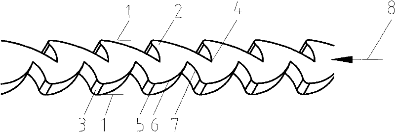
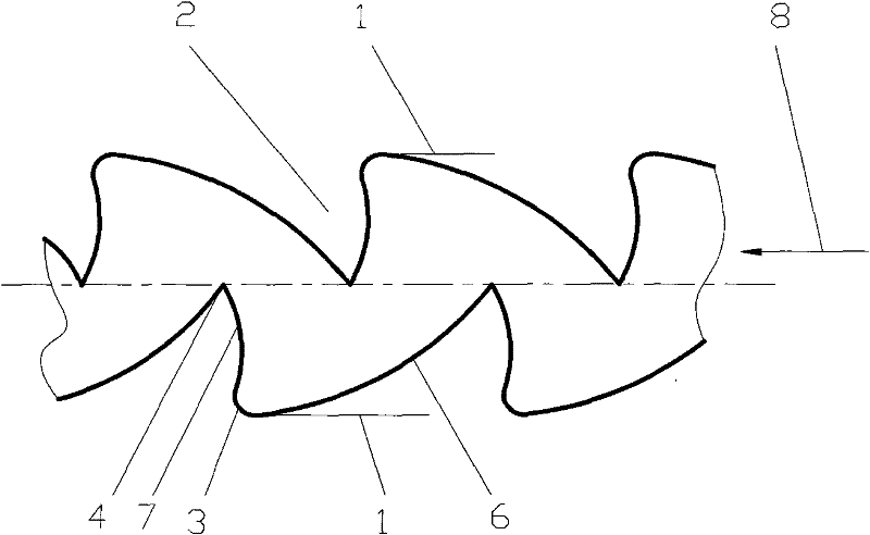
[0028] Such as figure 1 , figure 2 As shown, a fishbone-shaped drip irrigation emitter flow channel is formed by the upper and lower boundaries 1 and the width 5 of the flow channel to form a groove-shaped flow channel. The tooth profile angle 2 of the lower boundary is arranged in a staggered manner; the tooth profile angle 2 is composed of two circular arcs of different sizes, wherein the center of the larger circular arc 6 is different from the center plane of the larger circular arc 6 located in the length direction of the flow channel. side, the center of the smaller arc 7 and the smaller arc 7 are located on the same side of the center plane in the length direction of the flow channel; the dedendum intersection angle of the two tooth profile angles 2 connected to each other is an arc chamfer 3; the tooth profile The tooth tip 4 of angle 2 is located on the center plane in the length direction of the flow channel or extends to the other side of the center plane in the l...

Embodiment 2

[0031] The product in Example 1 is used in the thin-walled (wall thickness can be increased under other pressures) drip irrigation belt in micro-pressure drip irrigation, and the following 5 kinds of implementation methods can be realized to be commercialized.

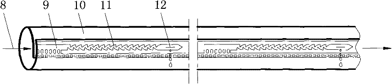
[0032] 1. Form a thin-walled laminated drip irrigation belt, such as image 3 as shown,

[0033] The flow channel 11 of the fishbone drip irrigation emitter of the present invention is formed into a thin-walled drip irrigation belt with the above-mentioned flow channel by staggering the inside and outside of the two side walls of the thin-walled plastic film and using plastic mold heat sealing or other bonding methods. The water end is bonded into a small granular filter water inlet 9, which is convenient for filtering larger impurities in the water. There is a larger water outlet pool at the water outlet end of the flow channel, and a small slit water outlet 12 is opened on the water outlet pool to facilitate water outl...


PUM


Abstract

The invention provides a fishbone drop irrigation douche runner, and an upper and lower boundary (1) and a runner depth (5) form a groove-shaped runner; the invention is characterized in that the upper and lower boundary (1) is formed by connection of more than two tooth-shaped angles (2) in sequence; the tooth-shaped angles (2); the tooth-shaped angles (2) of the upper boundary and the lower boundary are in staggered arrangement; the tooth-shaped angle (2) is formed by two circular arcs with different sizes, wherein, the circle center of a bigger circular arc (6) and the bigger circular arc (6) are positioned at the different sides of the central surface of the length direction of the runner; and the circle center of a smaller circular arc (7) and the small circular arc (7) are arranged at the same side of the central surface of the length direction of the runner. The fishbone drop irrigation douche runner of the invention is in a tooth-shaped angle runner structure which is formed by the circular arcs. The structure can lead the water in the runner to generate the function of stronger turbulent flow under a certain pressure; on one hand, the hydraulic performance of the douche can be improved, and the blockage resisting capacity of the douche is enhanced on the other hand.

Description

technical field [0001] The invention belongs to the technical field of drip irrigation for agricultural machinery, and in particular relates to a flow path of a fishbone-shaped drip irrigation dispenser. Background technique [0002] As we all know, picking irrigation is the most advanced high-standard irrigation technology in the world at present, and it is an effective way to develop cost-effective, high-yield, high-quality, and efficient agriculture. Countries all over the world are vigorously promoting this technology. In the drip irrigation system, the dripper is the tail equipment in the drip irrigation system and the key component of the drip irrigation system. Its performance directly affects the irrigation quality of the drip irrigation system. Dripper clogging has always been the main cause of equipment failure, and clogging is mainly caused by impurities in water, fertilizers, liquid medicines or chemical substances and microorganisms that block the narrow flow c...

Claims


Application Information

Patent Timeline
Patent Type & Authority Patents(China)
IPC IPC(8): B05B1/20B05B1/34
Inventor 方部玲耿华娟齐松涛
Owner HOHAI UNIV
Why Eureka
Try Eureka