
Inflation type cervical vertebrae rehabilitation device and method for using the same

a cervical vertebrae and rehabilitation device technology, applied in the field of inflation-type cervical vertebrae rehabilitation devices, can solve the problems of user discomfort, portable cervical vertebrae traction devices cannot be used for users who wear conventional cervical collars, cervical vertebrae,

Inactive Publication Date: 2011-07-14
CHINA MEDICAL UNIVERSITY(TW)
View PDF24 Cites 36 Cited by
  • Summary
  • Abstract
  • Description
  • Claims
  • Application Information

AI Technical Summary

Benefits of technology

"The present invention is an inflation type cervical vertebrae rehabilitation device and method for using it. The device has a cervical vertebrae cell for supporting the user's head and neck with rehabilitation functions. It also has a head cell for supporting the user's head and adjusting its height when the user lies down. The device has an electric inflation portion for inflating or deflating the cervical vertebrae cell and the head cell. The control portion controls the electric inflation portion. The method for using the device includes a preparing step, a setting inflation processes step, an inflating step, and a completion step. The device also has a heat unit, an audio unit, at least one orientation detection unit, and a wireless unit for providing warming, audio instruction, and remote-controlled features. The technical effects of the invention include providing a comfortable and effective way to support the user's head and neck during rehabilitation, as well as offering a variety of additional features such as heating, audio instruction, and remote control."

Problems solved by technology

However, the conventional cervical collar makes the user to feel uncomfortable.
The portable cervical vertebrae traction device cannot be used for the user who wears the conventional cervical collar.
In addition, there are no inflation members to support the cervical vertebrae and the device cannot be controlled by a wireless device.

Method used


Image

  • Inflation type cervical vertebrae rehabilitation device and method for using the same
  • Inflation type cervical vertebrae rehabilitation device and method for using the same
  • Inflation type cervical vertebrae rehabilitation device and method for using the same

Examples


Embodiment Construction

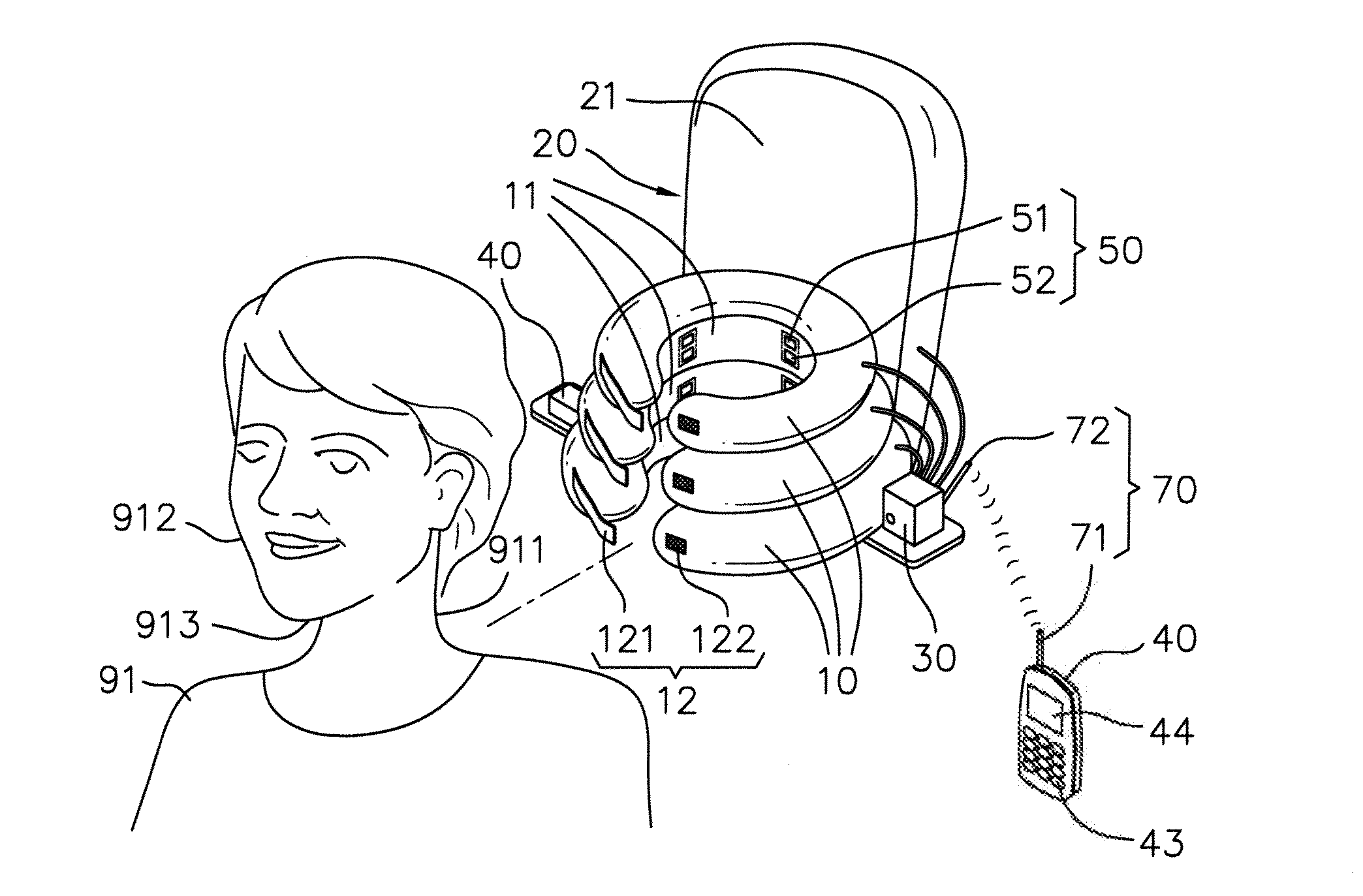
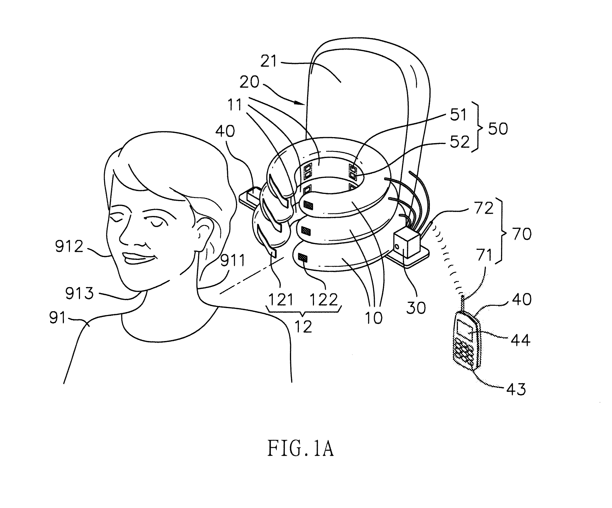
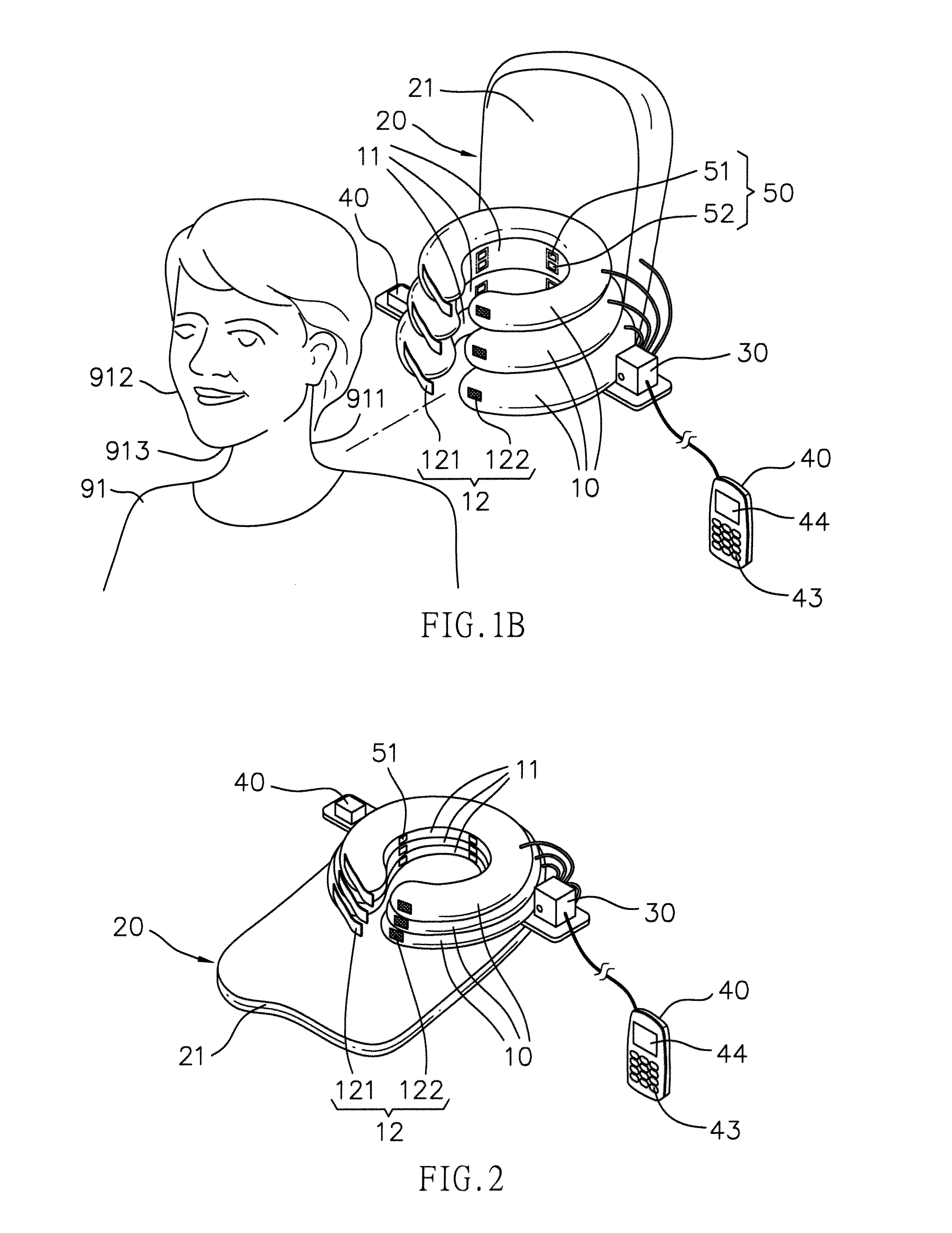
[0033]Referring to FIGS. 1A, 2, 3 and 5, the inflation type cervical vertebrae rehabilitation device of the present invention comprises at least one cervical vertebrae cell 10 for mounting the neck 911 of a user 91, and the at least one cervical vertebrae has a contact area 11 which is in contact with the neck 911. The at least one cervical vertebrae cell 10 is positioned between at least one support position P1 and at least one operation position P2 to support and rehabilitate the user' s cervical vertebrae.

[0034]A head cell 20 has a contact surface 21 and is connected to the at least one cervical vertebrae cell 10. The head cell 20 is positioned between an auxiliary support position P3 and an auxiliary adjusting position P4. The contact surface 21 supports the head 912 of the user 91 and adjusts height of the head 912 of the user 91 when the user 91 lies down as shown in FIG. 6.

[0035]An electric inflation portion 30 is used to inflate (FIG. 1A) or deflate (FIG. 2) the at least one...


PUM


Abstract

An inflation type cervical vertebrae rehabilitation device includes at least one cervical vertebrae cell, a head cell connected to the at least one cervical vertebrae cell, an electric inflation portion and a control portion. The method includes a preparing step, a setting inflation processes step, an inflating step, and a completion step. One or more cervical vertebrae cells are inflatable and positioned between a support position and an operation position to support and rehabilitate the user's neck. The head cell is provided to support the user's head. So, the cervical vertebrae cells can support the user's head and neck with rehabilitation functions. The head cell is an auxiliary for support the user's head. It is easy to carry. This invention could be remote controlled. It contains the far infra-red heating function. In addition, there is a pose balance feature.

Description

FIELD OF THE INVENTION[0001]The present invention relates to an inflation type cervical vertebrae rehabilitation device and a method for using the device.[0002][1] The cervical vertebrae cells can support the user's head and neck with rehabilitation functions.[0003][2] The head cell is an auxiliary for support the user's head.[0004][3] It is easy to carry.[0005][4] This invention could be remote controlled.[0006][5] It contains the far infra-red heating function.[0007][6] There is a pose balance feature.BACKGROUND OF THE INVENTION[0008]A conventional s used to protect the cervical vertebrae and which includes a steel frame coated with soft pad. However, the conventional cervical collar makes the user to feel uncomfortable. A portable cervical vertebrae traction device is developed and shown in FIG. 16 and generally includes a frame 92 which is fixed to a wall and a cable 93 goes around the frame 92 and one end of the cable 93 is connected with a weight 94 and the other end of the ca...

Claims


Application Information

Patent Timeline
Patent Type & Authority Applications(United States)
IPC IPC(8): A61F5/00
CPCA61F5/012A61N2005/066A61N5/0625A61F5/055
Inventor CHIU, CHING-HUACHOU, LI-WEI
Owner CHINA MEDICAL UNIVERSITY(TW)
Learn More