Video display apparatus and video display method

a video display and video display technology, applied in the field of video display apparatus and video display method, can solve the problems of blurred moving image and no satisfactory method developed

Inactive Publication Date: 2011-07-21
KK TOSHIBA
View PDF7 Cites 25 Cited by
  • Summary
  • Abstract
  • Description
  • Claims
  • Application Information

AI Technical Summary

Problems solved by technology

In liquid crystal TV receivers, a moving image is blurred because of low response speed of the liquid crystal.
However, whereas 3D display has come to be employed in recent years, no satisfactory methods have been developed which vary the backlight turn-on timing when switching is made between the 2D display and the 3D display of a display panel.

Method used


Image

  • Video display apparatus and video display method
  • Video display apparatus and video display method
  • Video display apparatus and video display method

Examples


embodiment 1

[0019]A first embodiment will be described below with reference to FIG. 1 to FIG. 7B.

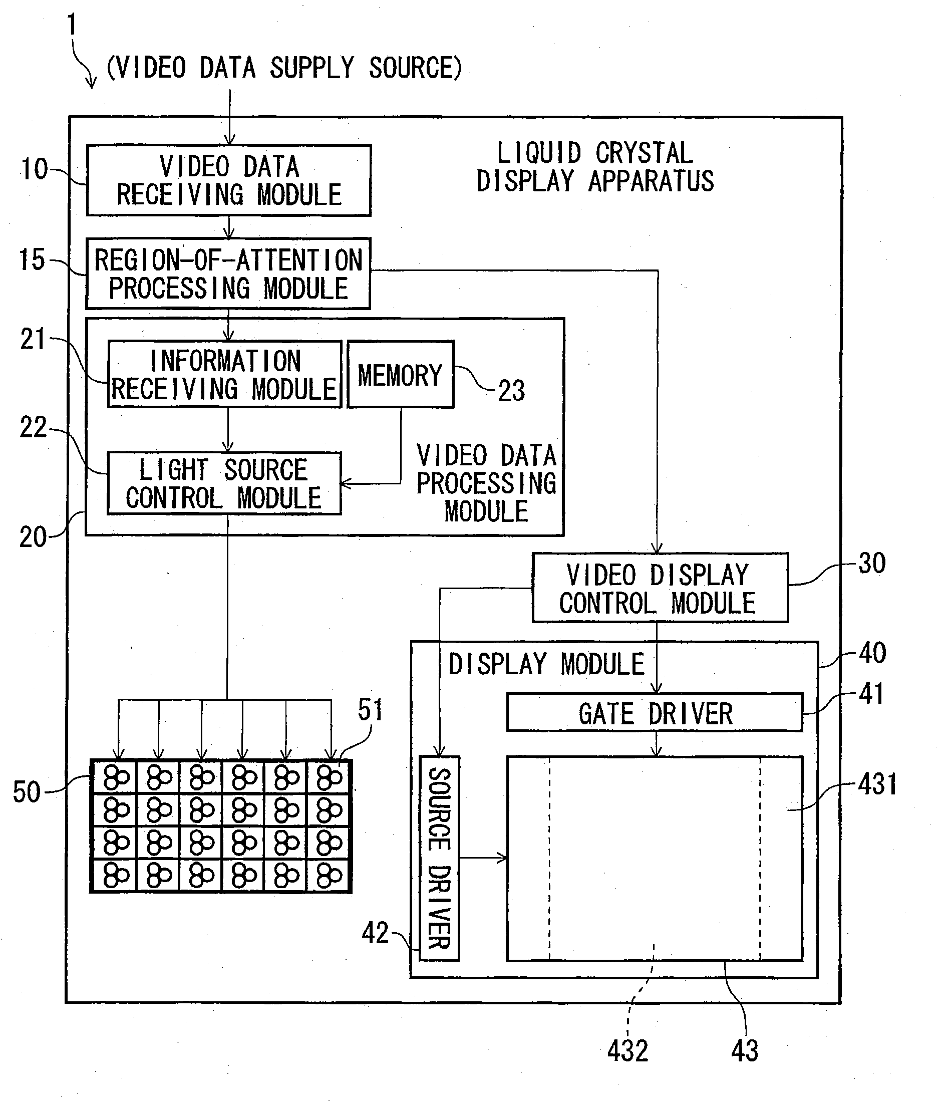
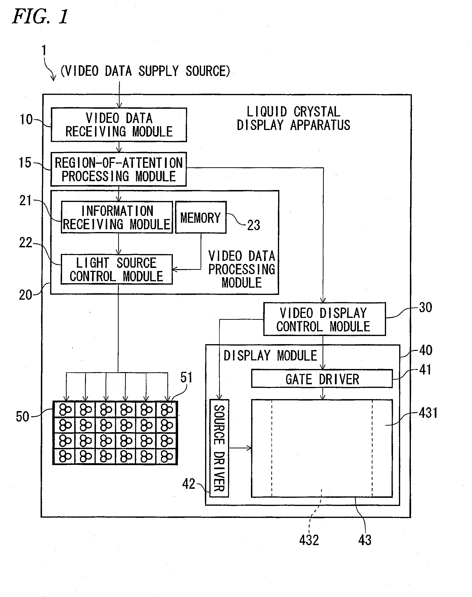
[0020]FIG. 1 is an exemplary block diagram showing the configuration of a liquid crystal display apparatus 1 according to the first embodiment. As shown in FIG. 1, the liquid crystal display apparatus 1 includes a video data receiving module 10, a region-of-attention processing module 15, a video data processing module 20, a video display control module 30, a display module 40, and a backlight 50 as a light source.

[0021]Connected to an outdoor antenna (not shown), for example, the video data receiving module 10 receives video data via the antenna. The video data receiving module 10 can receive various kinds of video data that are carried by terrestrial analog waves, terrestrial digital waves, satellite broadcast waves, etc. The video data receiving module 10 can also be connected to any of various video playback apparatus (e.g., HD DVD player, HD DVD recorder, DVD player, and DVD recorder). When con...

embodiment 2

[0052]A second embodiment will be described below with reference to FIGS. 1-9. Modules etc. having the same ones in the first embodiment will not be described in detail.

[0053]It is known that the response speed of the liquid crystal is also affected by temperature, that is, as shown in FIG. 8 the response speed decreases as temperature becomes lower. In view of this, in this embodiment, a temperature sensor is incorporated in the lighting timing generation processing module 103 or temperature information is received from the outside. A control is performed so that as shown in FIG. 9 the turn-on timing is delayed further when the temperature is low. This measure can reduce the influence of the decrease in response speed. In the example of FIG. 9, the lighting period is made shorter according to the delay of the turn-on timing. This is to prevent a phenomenon that when the lighting period is unduly long, video of the next frame appears because of leak light between the lines of the ba...


PUM


Abstract

In general, according to one embodiment, a video display apparatus includes a backlight, a signal processing module, a transmission-type display panel, and a lighting timing generation processing module. The signal processing module is configured to process an input video signal and output an output video signal for 2D display or 3D display. The transmission-type display panel is configured to control transmission of light supplied from the backlight according to the output video signal. The lighting timing generation processing module is configured to switch between a backlight lighting period for the 2D display and a backlight lighting period for the 3D display in such a manner that a time of a center of gravity of a figure formed by a response level-time curve in the backlight lighting period is later in the 3D display than in the 2D display.

Description

CROSS REFERENCE TO RELATED APPLICATION(S)[0001]This application is based upon and claims the benefit of priority from Japanese Patent Application No. 2010-011429 filed on Jan. 21, 2010, entire contents of which are incorporated herein by reference.BACKGROUND[0002]1. Field[0003]Embodiments described herein relate generally to a video display apparatus and a video display method.[0004]2. Description of the Related Art[0005]In liquid crystal TV receivers, a moving image is blurred because of low response speed of the liquid crystal. One common countermeasure is to turn on the backlight with such timing that a response of the liquid crystal has completed and target video has been rendered well displayable. However, whereas 3D display has come to be employed in recent years, no satisfactory methods have been developed which vary the backlight turn-on timing when switching is made between the 2D display and the 3D display of a display panel.BRIEF DESCRIPTION OF THE SEVERAL VIEWS OF THE DR...

Claims


Application Information

Patent Timeline
Patent Type & Authority Applications(United States)
IPC IPC(8): H04N13/04
CPCH04N13/0497H04N13/0454H04N13/359H04N13/398
Inventor ITO, KEN
Owner KK TOSHIBA
Why Eureka
Try Eureka