Motion calculation device and motion calculation method

a technology of motion calculation and calculation method, which is applied in the field of motion calculation device and motion calculation method, can solve the problems of difficult to calculate the motion of the host device based on the epipolar constraint relating to the feature, and difficult to calculate the motion of the host device based on the homography relating to the plane, so as to achieve the effect of minimizing the cost function

Inactive Publication Date: 2011-07-21
HONDA ELESYS CO LTD
View PDF22 Cites 22 Cited by
  • Summary
  • Abstract
  • Description
  • Claims
  • Application Information

AI Technical Summary

Benefits of technology

In the motion calculation device, the calculation unit may minimize a cost fu...

Problems solved by technology

However, in the motion measurement device described in JP-A-2006-350897, there is a problem in that, when there are a small number of feature points corresponding to, for example, a stationary object in an image captured by an image-capturing unit, it is very difficult to calculate the motion of the host device based on the epipol...

Method used


Image

  • Motion calculation device and motion calculation method
  • Motion calculation device and motion calculation method
  • Motion calculation device and motion calculation method

Examples


first embodiment

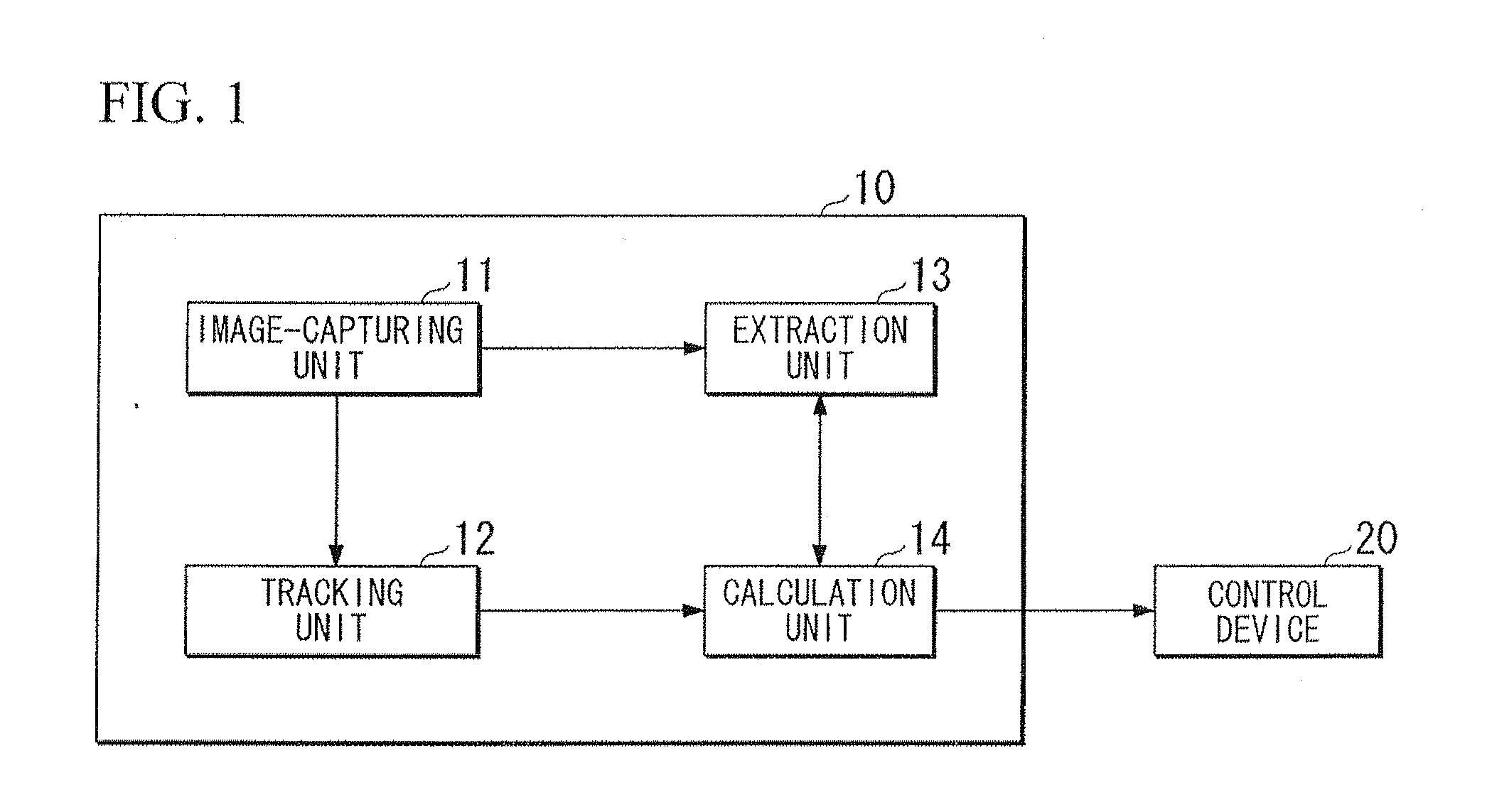
A first embodiment of the invention will be described in detail with reference to the drawings, FIG. 1 is a block diagram showing the configuration of a camera system. A camera system is provided in a mobile object. The mobile object is, for example, a vehicle. The camera system includes a motion calculation device 10, and a control device 20.

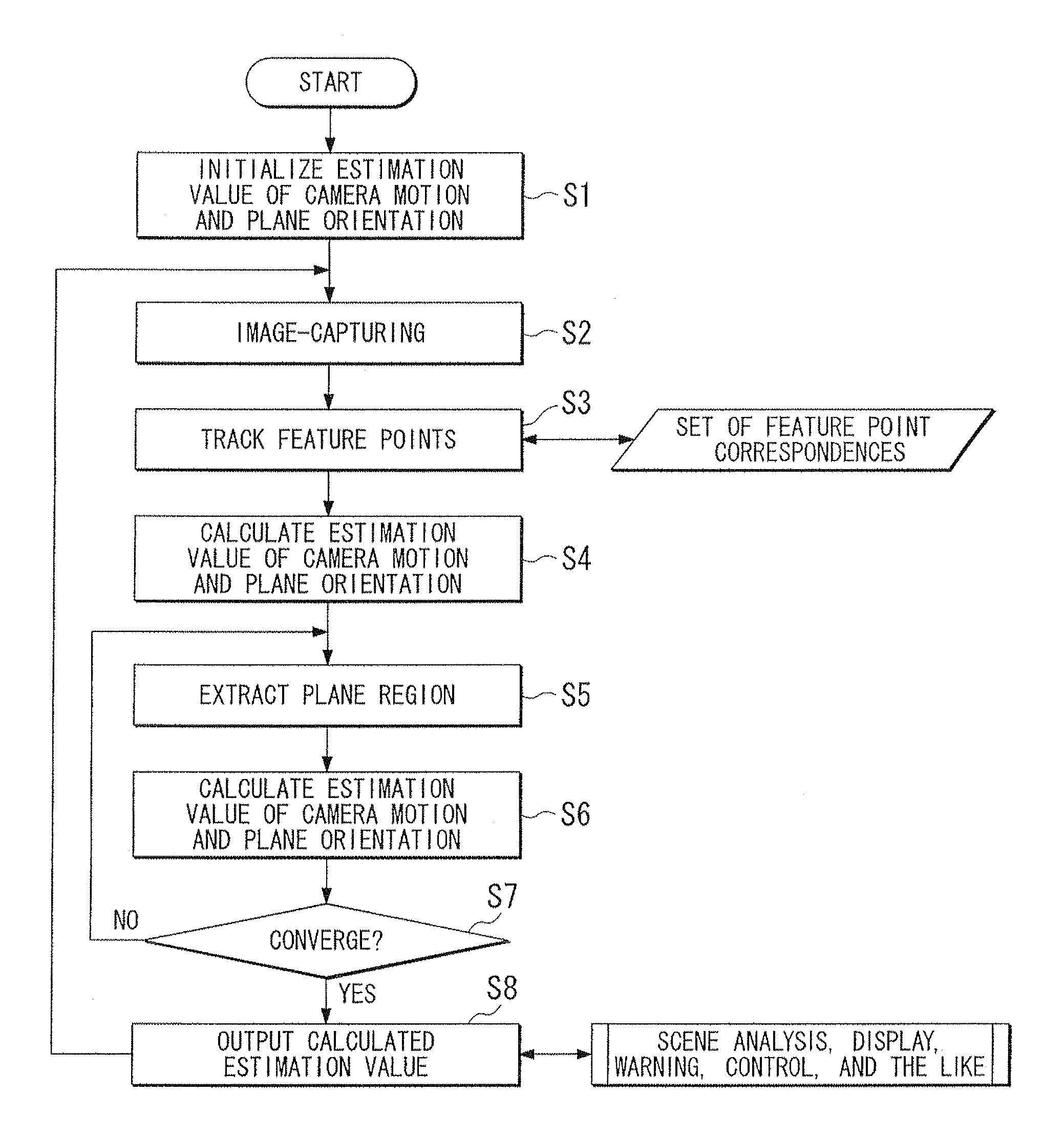
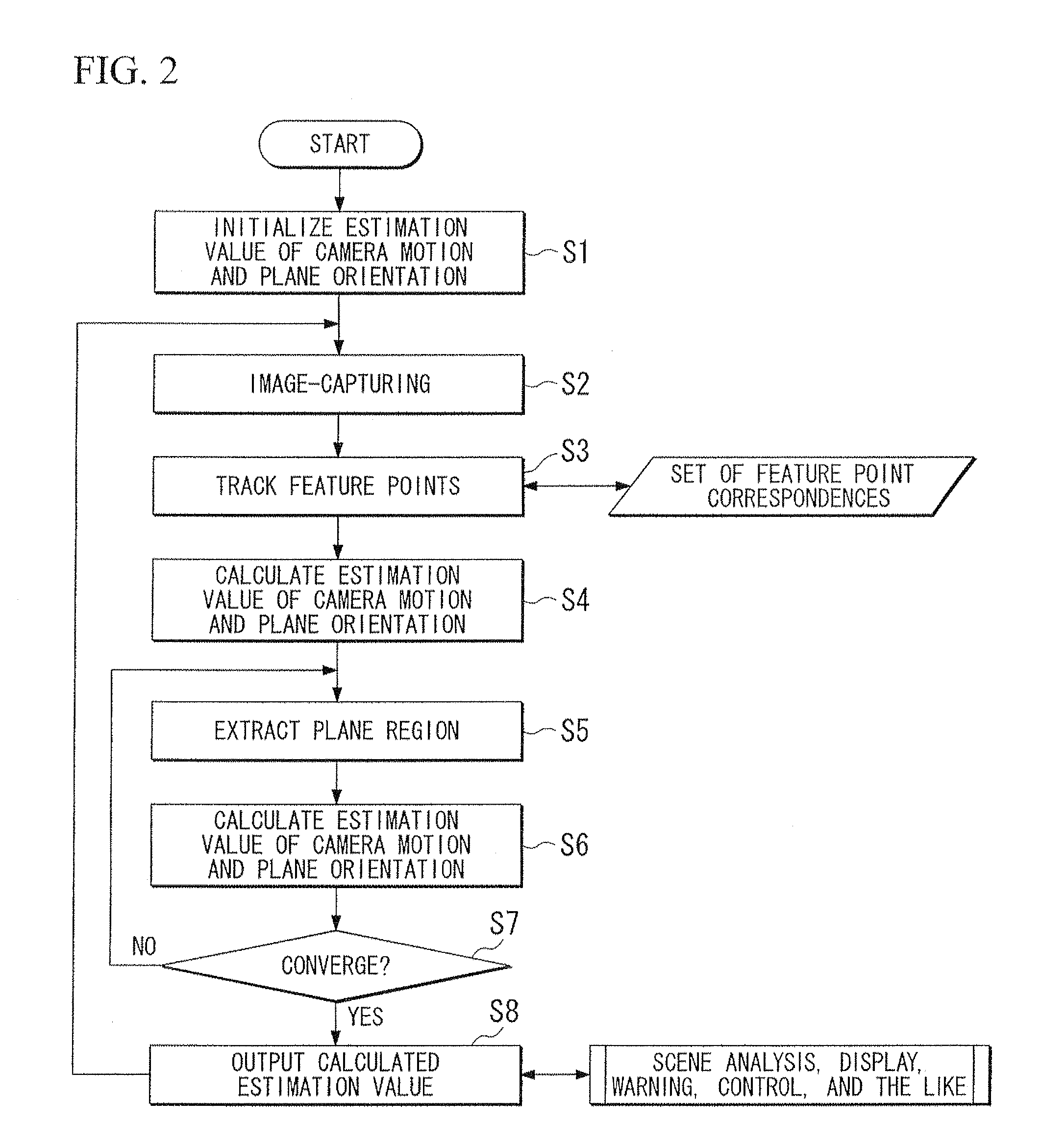
The motion calculation device 10 captures an image of a range including a plane (for example, the ground) and calculates the motion (hereinafter, referred to as a “camera motion”) of the host device based on the captured image. The motion calculation device 10 outputs the calculated camera motion to the control device 20.

The motion calculation device 10 includes an image-capturing unit 11, a tracking unit (detection unit) 12, an extraction unit 13, and a calculation unit 14. The image-capturing unit 11 includes a light-receiving element, and the light-receiving surface of the light-receiving element has a plurality of pixels. An optical image i...

second embodiment

A second embodiment of the invention will be described in detail with reference to the drawings. In the second embodiment, the regularization term of the cost function is different from that in the first embodiment. Hereinafter, a description will be provided of only differences from the first embodiment.

When it is assumed that the distance d between the principal point of the image-capturing unit 11 (see FIG. 1) and the plane is substantially constant, the speed information (the magnitude of the translation vector) v of the host device may not be included in the regularization term (third term) in Expression (1). The relationship |n|2=d−2 is established when the distance d between the principal point of the image-capturing unit 11 and the plane expressed by nTP=1 is expressed by d=−1 / |n|. Thus, when it is assumed that the distance d between the principal point of the image-capturing unit 11 to the plane is substantially constant, the cost function is expressed by Expression (20),

Qd...


PUM


Abstract

A motion calculation device includes an image-capturing unit configured to capture an image of a range including a plane and outputs the captured image, an extraction unit configured to extract a region of the plane from the image, a detection unit configured to detect feature points and motion vectors of the feature points from a plurality of images captured by the image-capturing unit at a predetermined time interval; and a calculation unit configured to calculate the motion of the host device based on both of an epipolar constraint relating to the feature points and a homography relating to the region.

Description

BACKGROUND OF THE INVENT1. Field of the InventionThe present invention relates to a motion calculation device and a motion calculation method which calculates the motion of the host device based on captured images.2. Description of Related ArtJP-A-2006-350897 describes a motion measurement device which measures the motion of a mobile object including image-capturing means based on an epipolar constraint relating to images captured by the image-capturing means.JP-T-2003-515827 describes a system which predicts the motion (egomotion) of transfer means including a camera based on a homography relating to the images captured by the camera.However, in the motion measurement device described in JP-A-2006-350897, there is a problem in that, when there are a small number of feature points corresponding to, for example, a stationary object in an image captured by an image-capturing unit, it is very difficult to calculate the motion of the host device based on the epipolar constraint relating...

Claims


Application Information

Patent Timeline
IPC IPC(8): H04N7/18G06K9/00
CPCG06K9/00798G06T2207/30244G06T2207/20164G06T7/2033G06T7/246G06V20/588
Inventor AZUMA, TAKAHIROOKUTOMI, MASATOSHISUGIMOTO, SHIGEKI
Owner HONDA ELESYS CO LTD
Why Eureka
Try Eureka