Clipping of transmission signal

a technology of transmission signal and strength restriction, which is applied in the direction of transmission monitoring, baseband system details, and generated signals, etc., can solve the problems of reducing the efficiency of amplifiers and/or transmitters, limiting the obtainable maximum transmit power, and high cost of power amplifiers with a broad linear operating range. achieve the effect of reducing the strength

Active Publication Date: 2006-07-13
RPX CORP
View PDF43 Cites 43 Cited by
  • Summary
  • Abstract
  • Description
  • Claims
  • Application Information

AI Technical Summary

Benefits of technology

[0005] According to another aspect of the invention, there is provided a transmitter in a radio system, the transmitter being configured to clip a transmission signal before transmission in order to reduce the strength of at least one peak of the transmission signal exceeding a predetermined threshold. The transmitter further comprises a clipper comprising a minimizer for minimizing of a cost function with respect to an optimisation signal the cost function having weighted terms as a function of the optimisation signal, the terms relating to an effective modulation distortion and an effective overshoot exceeding the predetermined threshold; a filter for forming a clipping signal by filtering the optimisation signal formed as a result of the minimization according to the spectrum emission mask requirements of the radio system; and an adder for subtracting the clipping signal from the transmission signal.

Problems solved by technology

In a radio system linearity of a power amplifier limits the obtainable maximum transmit power, especially when the signal to be transmitted has a high peak to average power ratio (PAPR).
However, this reduces the efficiency of the amplifier and / or the transmitter.
Secondly, power amplifiers with a broad linear operating range are expensive.
However, a problem with the clipping methods is that the signal frequency spectrum spreads, i.e. usually the spectrum spreads beyond the frequency band that is used, thus causing interference to other users.

Method used


Image

  • Clipping of transmission signal
  • Clipping of transmission signal
  • Clipping of transmission signal

Examples


Embodiment Construction

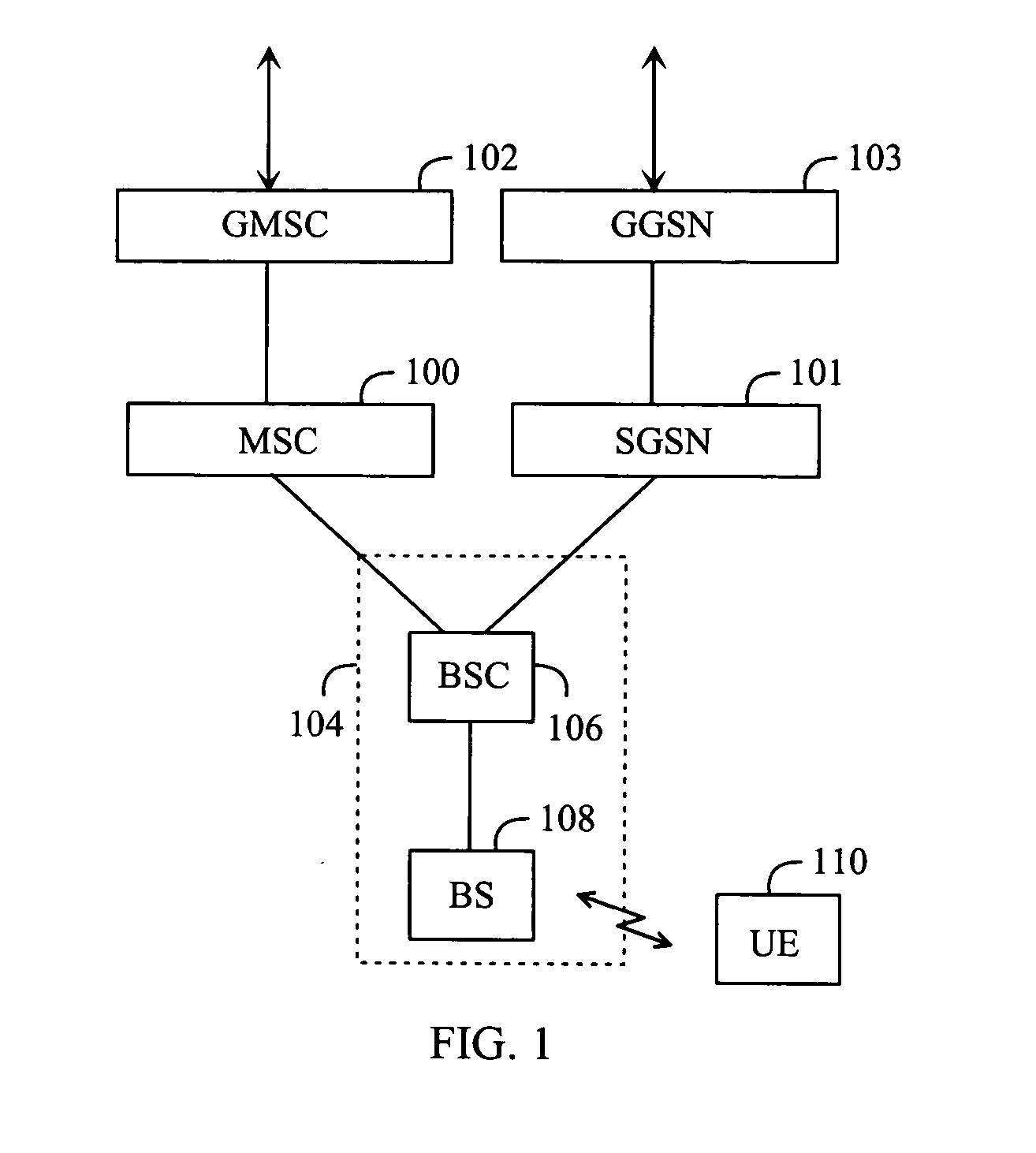
[0021] Let us first study FIG. 1 that illustrates the structure of a radio system. The radio system can be based on, for example, UMTS (Universal Mobile Telephone System) or WCDMA (Wide-band Code Division Multiple Access).

[0022] The core network may, for example, correspond to the combined structure of the GSM (Global System for Mobile Communications) and GPRS (General Packet Radio Service) systems. The GSM network elements are responsible for the implementation of circuit-switched connections, and the GPRS network elements for the implementation of packet-switched connections, some of the network elements being, however, shared by both systems.

[0023] A mobile services switching centre (MSC) 100 enables circuit-switched signalling in the radio system. A serving GPRS support node (SGSN) 101 in turn enables packet-switched signalling. All traffic in the radio system may be controlled by the MSC 100.

[0024] The core network may have a gateway unit 102, which represents a gateway mobi...


PUM


Abstract

A transmitter clips a transmission signal before transmission in order to reduce the strength of at least one peak of the transmission signal exceeding a predetermined threshold. The transmitter includes a clipper having a minimizer, a filter and an adder. The minimizer minimizes of a cost function with respect to an optimization signal, the cost function having weighted terms as a function of the optimization signal. The terms relate to an effective modulation distortion and an effective overshoot exceeding the predetermined threshold. The filter forms a clipping signal by filtering the optimization signal formed as a result of the minimization according to the spectrum emission mask requirements of the radio system. The adder subtracts the clipping signal from the transmission signal.

Description

FIELD [0001] The invention relates to restriction of strength of a signal in a radio transmitter. BACKGROUND [0002] In a radio system linearity of a power amplifier limits the obtainable maximum transmit power, especially when the signal to be transmitted has a high peak to average power ratio (PAPR). In such a case the signal input to the power amplifier may exhibit momentarily high power that must be taken into account in designing the power amplifier. This means in practice that an output signal of the amplifier is scaled down to a lower power level in order to meet the spectral requirements of the data transmission system currently in use. Due to this, the signal to be amplified is biased such that the transfer function of the amplifier becomes more linear. However, this reduces the efficiency of the amplifier and / or the transmitter. Secondly, power amplifiers with a broad linear operating range are expensive. [0003] Signal components exceeding a threshold can also be clipped by...

Claims


Application Information

Patent Timeline
Patent Type & Authority Applications(United States)
IPC IPC(8): H04B1/04H04B17/00H03F1/06H03F1/32H04LH04L27/26
CPCH03F1/0205H03F1/32H03F2201/3236H04B1/04H04B2001/0416H04L27/2623
Inventor PIIRAINEN, OLLI
Owner RPX CORP
Why Eureka
Try Eureka