Cable mounting structure for electric apparatus

Active Publication Date: 2011-07-28
MEIDENSHA ELECTRIC MFG CO LTD
View PDF9 Cites 10 Cited by
  • Summary
  • Abstract
  • Description
  • Claims
  • Application Information

AI Technical Summary

Benefits of technology

[0020]With the cable mounting structure for an electric apparatus according to the present invention, the recessed section is formed in a closed-bottomed tubular shape recessed inwardly of the housing, the fixing section for fixing the grommet mounted on the cable is provided in the peripheral wall section of the recessed section, and the pass-through section through which the cable is passed is provided in the lid, and the connecting tool is disposed within the recessed section, and the pass-through section is positioned to the grommet. Thus, the sealing properties such as waterproof properties and dustproof properties can be ensured. Regardless of the size of the pass-through section, the connecting tool can be disposed within the recessed section, and restrictions on the size of the connecting tool can be eased. Furthermore, the grommet and the connecting tool can be disposed within the recessed section of the housing. Thus, this configuration can effectively contribute to down

Problems solved by technology

Thus, it has been difficult to achieve downsizing.
As

Method used


Image

  • Cable mounting structure for electric apparatus
  • Cable mounting structure for electric apparatus
  • Cable mounting structure for electric apparatus

Examples


Example

[0030]A cable mounting structure for an electric apparatus according to a first embodiment of the present invention will be described by reference to FIGS. 1 to 4.

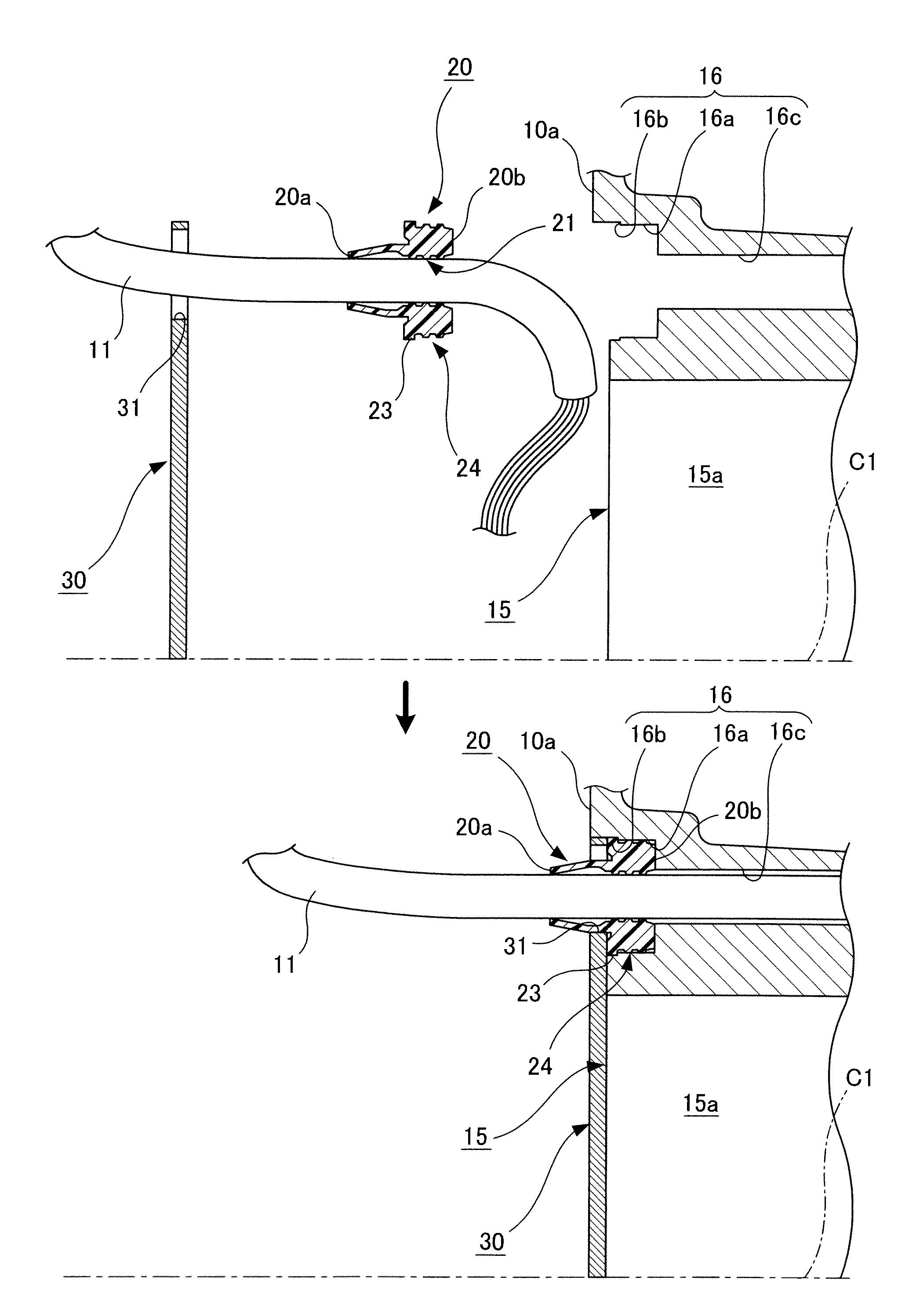
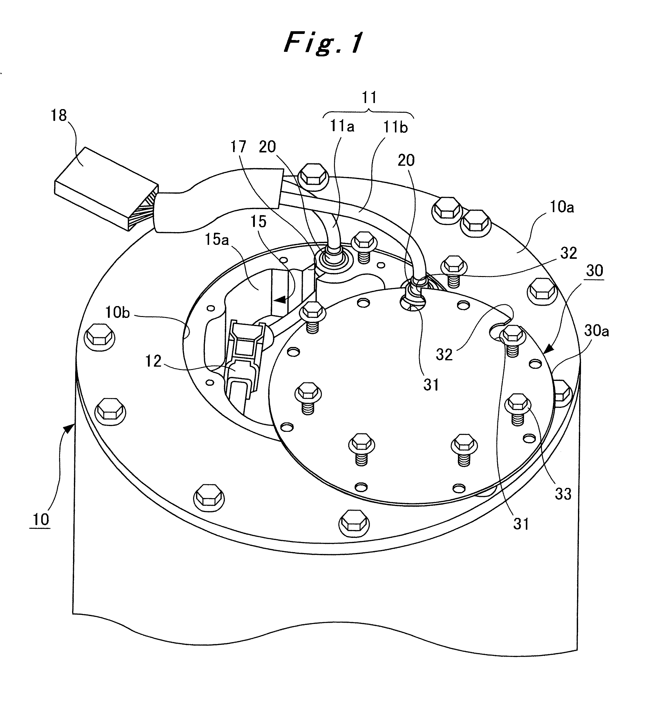
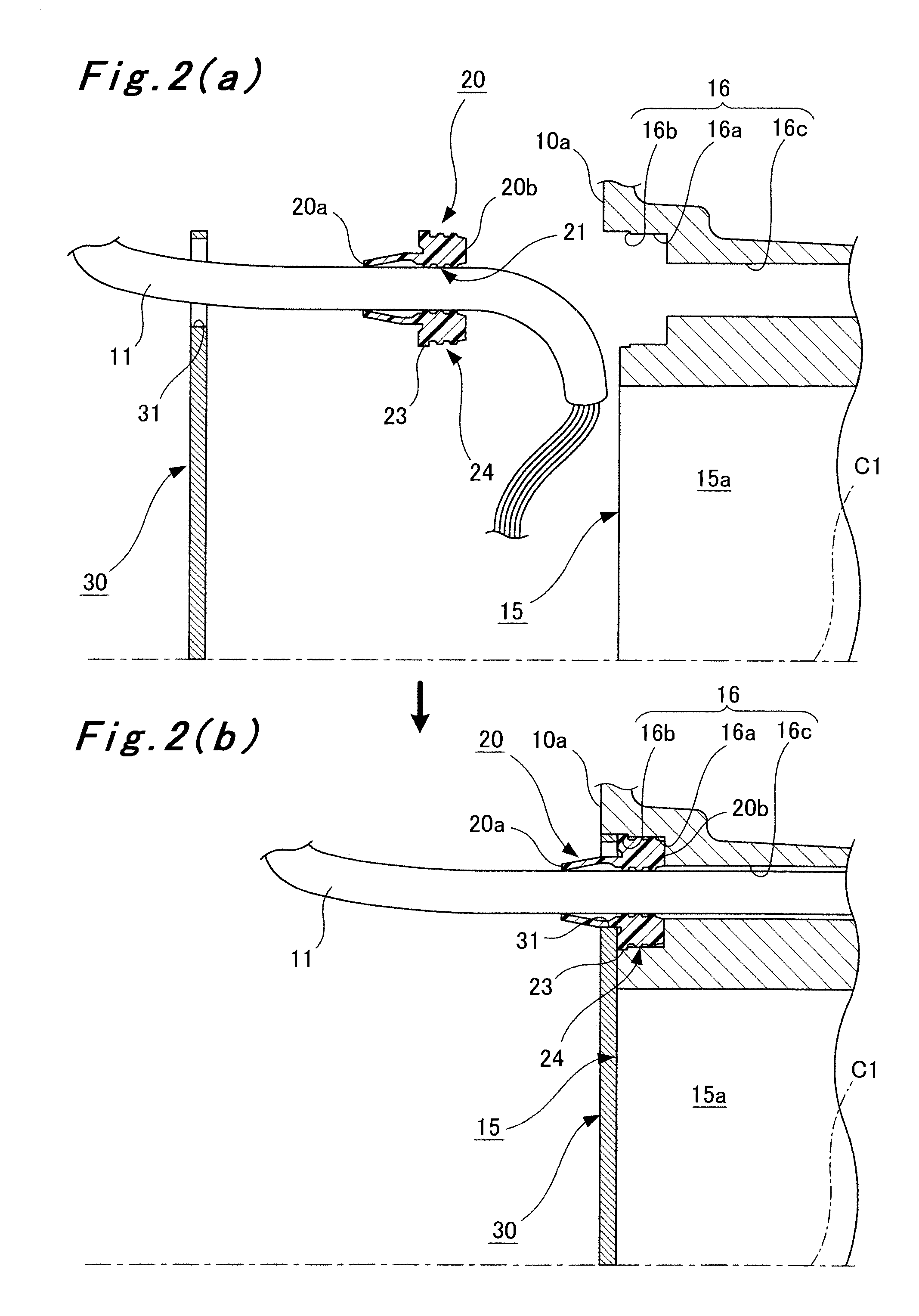
[0031]The cable mounting structure for an electric apparatus according to the first embodiment of the present invention, as shown in FIG. 1, is a cable mounting structure for an electric apparatus, adapted to mount a cable 11, which connects an electric apparatus body 1 to the outside of a nearly cylindrical housing 10 for accommodating the electric apparatus body 1, to the housing 10. The cable mounting structure is provided on one end 10a of the housing 10. As the electric apparatus body 1, there is named the one required to have waterproof properties and dustproof properties depending on an environment for its use, for example, an electric rotating machine having a stator and a rotor.

[0032]The cable 11 has a first cable 11a and a second cable lib. The first cable 11a has one end (end facing the electric apparatus body 1...


PUM


Abstract

A cable mounting structure for an electric apparatus is provided which ensures sealing properties, such as waterproof properties and dustproof properties, and which can effectively contribute to downsizing, while easing restrictions on the size of a connecting tool mounted on one end of a cable connected to an electric apparatus body. The cable mounting structure comprises a housing (10) for accommodating an electric apparatus body, a cable (11) connected to the electric apparatus body via a second connector (12) or the like, a grommet (20) mounted on the cable (11), a recessed housing section (15) provided in the housing (10), and a lid (30) for closing the recessed housing section. The recessed housing section is formed in a closed-bottomed tubular shape recessed inwardly of the housing. A grommet mounting hole for fixing the grommet (20) thereto is formed in a peripheral wall section (15a) of the recessed housing section, and a pass-through section (31) through which the cable is passed is formed in the lid. The connecting tool is disposed within the recessed housing section, and the pass-through section is positioned to the grommet.

Description

TECHNICAL FIELD[0001]This invention relates to a cable mounting structure for an electric apparatus.BACKGROUND ART[0002]An electric apparatus is required to have waterproof properties and dustproof properties in order to prevent a failure or a malfunction in the electric apparatus itself which may occur depending on an environment where it is used. As a method for fulfilling such a requirement, there is adopted, for example, a technique in which an electric apparatus body is accommodated within a closed or sealed housing. Even with such a technique, the electric apparatus body accommodated in the housing needs to be connected to the outside of the housing with the use of a cable, with the aim of supplying electric power from outside to the electric apparatus body, or transmitting and receiving control signals and data signals for the electric apparatus body. For this purpose, a cable mounting structure for the electric apparatus is also required to have waterproof properties and dus...

Claims


Application Information

Patent Timeline
IPC IPC(8): H02G3/18
CPCF16J15/106H02G3/22Y10T16/05H02K5/225Y10T16/063H02G15/013
Inventor NAGATA, KOJIHIGASHI, YOSHITAKA
Owner MEIDENSHA ELECTRIC MFG CO LTD
Why Eureka
Try Eureka